No. 01 of 20 · Round lids only
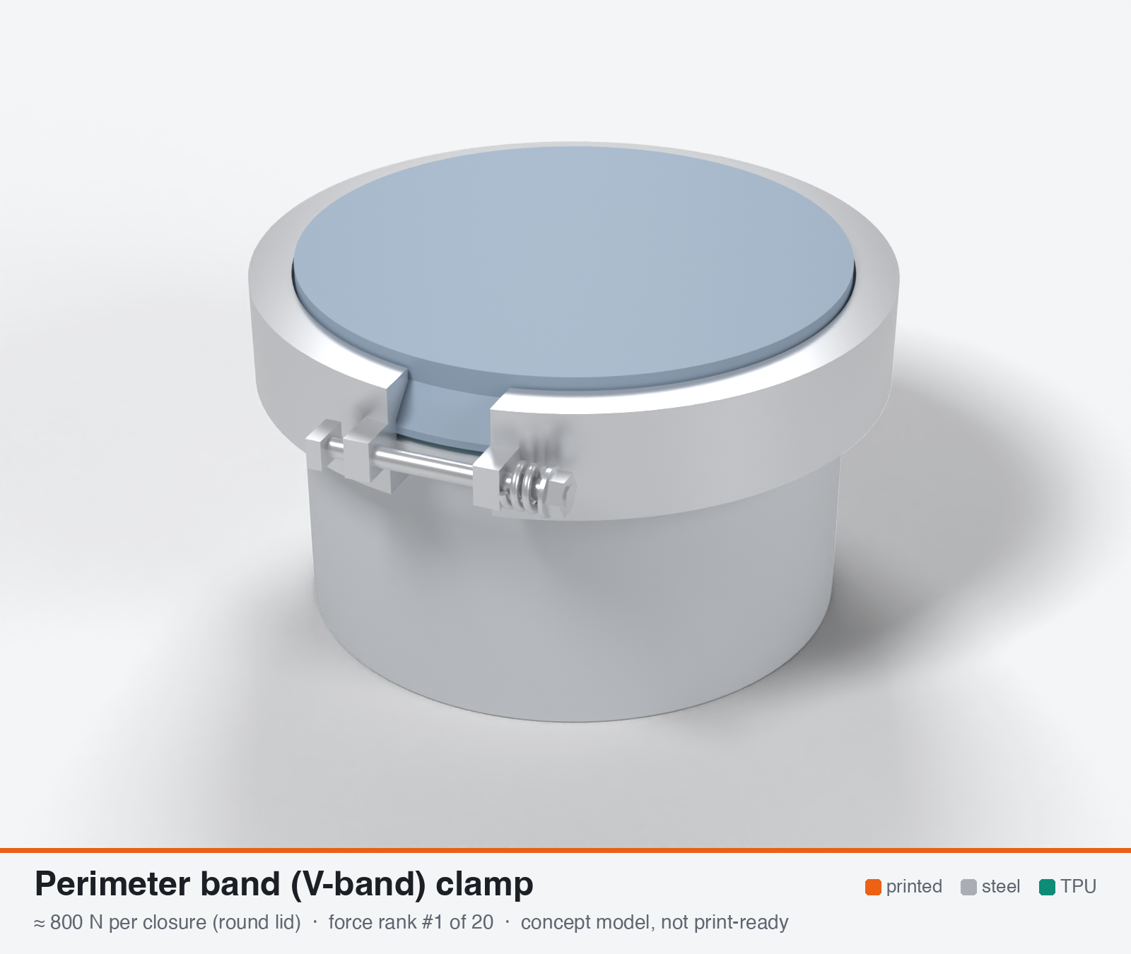
Perimeter band (V-band) clamp
Perimeter band clamp (V-band / Marman / flange clip clamp / strap buckle band)
Round lids only. The force below is for one whole closure, not one latch on a rectangular lid.
- Force rank
- 1 of 20
- Rank for outdoor sealing
- 6
- Build
- Printed + steel hardware
- Hand force to close
- ≈ 25 N
- Adjustable preload
- yes
- Positive compression stop
- yes
- Force basis
- calculated
- Review verdict
- corrected
- Confidence
- medium
Verdict: Highest number but it is a whole-closure force for one steel band on a ROUND or oval lid (about 2.1 N/mm on a 377 mm path), not a per-latch force. It does not fit the 70x35x30 mm envelope or the 200x150 mm rectangle. A 10x8 mm printed ring and a spring in the T-bolt are required.
Why it ranks #6 for sealing: Conditional on a ROUND or oval lid of about 100-200 mm. About 800 N per closure (about 2.1 N/mm on a 120 mm lid), with a uniform line load that removes the rim-bending pitch problem. Use a stainless band, 10x8 mm or metal-reinforced rings, and a spring in the T-bolt. Not a per-latch number and not usable on a rectangular lid. For round lids it would rank near the top.
On this page
- Parts
- Print files
- How it works
- Mechanical advantage
- What limits the force
- Analyst's calculation
- Adversarial review
- Calibration adjustments
- Preload retention outdoors
- Materials
- Hardware notes from the research
- Design guidelines
- Failure modes
- Existing designs and commercial references
- Evidence gathered in the sweep
- Sources
Parts
Per closure: 2 parts to print, 1 item to buy and the TPU 85A seal. In the 3D gallery you can click a part to see where it sits. The last column links the print file, or an example of the part in a shop (see the shopping list).
| Part | Qty | Type | What to use | File or shop |
|---|---|---|---|---|
| Container with V-flange | 1 | ASA, upright; the flange has a seal groove and a raised land that the lid lands on (the hard stop) | container.stl | |
| Lid with V-flange | 1 | ASA, upside down; flange ring 8.5 × 6.5 mm in section | lid.stl | |
| Seal ring | 1 | Seal (TPU 85A) | TPU 85A, 1.5 × 3.4 mm, in the flange groove; the band squeezes it 0.8 mm | seal-ring.stl |
| Band clamp | 1 | Buy | Stainless band clamp for about 120 mm: ideally a constant-tension T-bolt clamp (a spring keeps the band tight as the seal creeps); a worm-drive hose clamp works for a test | Inox Store |
Print files
Download all print files for this closure (ZIP, 98 kB)
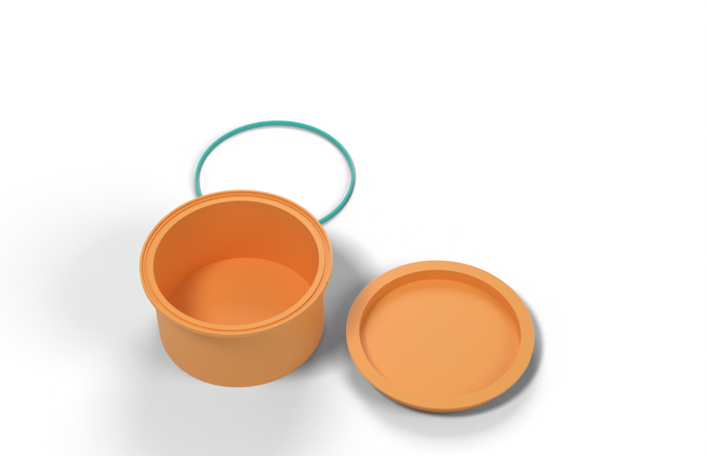
Print in ASA (TPU 85A for the seal), 0.2 mm layers, at least 4 walls; settings and the clearances used are in print/README.md. The parts are already turned the right way up for printing.
| File | Material | Qty | Size (mm) | How to print |
|---|---|---|---|---|
| container.stl | ASA | 1 | 122 × 122 × 61.6 | Upright, open end up, no supports (the flange cone is 43 degrees). The raised outer land is the hard stop the lid lands on; the seal ring sits in the groove inside it. |
| lid.stl | ASA | 1 | 122 × 122 × 12.9 | Upside down, flat top on the bed, no supports. |
| seal-ring.stl | TPU 85A | 1 | 115.5 × 115.5 × 3.4 | TPU 85A, 100 % infill. Sits in the container groove 2.4 mm proud; the band squeezes it 0.8 mm. |
All printed parts in their assembled positions, for CAD: perimeter-band-clamp.step.
How it works
A band or hinged ring halves with V-shaped (about 20 deg) shoes is tensioned around matching conical or chamfered flanges on lid and body. The tension gives a radial line load T/r. The wedge faces turn that radial load into an axial force pushing the two flanges together, around the whole perimeter, so the gasket is loaded uniformly instead of at points. The tension comes from a T-bolt, thumbscrew or over-centre buckle. Only round or oval flanges work. Straight spans of a rectangular lid do not take hoop-wedge loading.
Mechanical advantage
Wedge: F_ax,total = pi T (1 - mu tan th)/(tan th + mu) with th = 20 deg (face angle to the flange plane) and mu = 0.3. That is 4.2 T ideal, and I use ~3 T after a 0.7 derate for circumferential friction and uneven tension. This is independent of band diameter (confirmed by Barrans et al. FEA for 20 deg half-section and T-bolt loads < 7 kN). The closure adds more: M5 T-bolt at K = 0.2 turns 0.3 N.m into T = 300 N, or an over-centre buckle at about 8:1. The axial stroke is only tan 20 = 0.36x the radial movement per face, which damps creep sensitivity.
What limits the force
The printed ring and flange, not the steel band. Hoop compression in the flange ring equals T (6 MPa at T = 300 N on an 8x6 mm section), and the radial line load T/r (5 N/mm at T = 300, r = 60) loads a thin printed shell near its buckling limit. A long 3 mm shell at R = 60 buckles at ~0.06 MPa (own calc). Printed clamp halves in tension carry only ~100-160 N (4x8 mm, 3-5 MPa), so a steel band plus thick or insert-reinforced rings is needed. Needs round or oval flanges, so per-latch comparison with other mechanisms is not meaningful. Numbers are the total axial force of the whole closure.
Analyst's calculation
Analyst's sustained estimate: 450–1800 N, typical 900 N; peak 3600 N.
Own derivation. Per wedge face the normal force is N, with axial component N(cos th - mu sin th) and radial component N(sin th + mu cos th), two faces per segment. Hence F_ax,total = pi T (1 - mu tan th)/(tan th + mu). For th = 20 deg: mu = 0.15 gives 5.8 T, mu = 0.30 gives 4.2 T, mu = 0.45 gives 3.2 T (rough printed cone faces fall at the low end). The radial load is 1.49x the axial line load at mu = 0.3. A linear axial-vs-T-bolt relation, independent of band diameter for T-bolt loads under 7 kN, is confirmed by Barrans et al. (Open Eng. 2015) with 20 deg half-section. They also report that wedge angle and friction strongly affect stiffness. The lead's 'over-predicts' remark was not found in that paper. With a 0.7 derate F_ax = 3 T. Example round lid D = 120 mm (circumference 377 mm). T = 150 / 300 / 600 N gives F = 450 / 900 / 1800 N, i.e. 1.2 / 2.4 / 4.8 N/mm line load. The 2-4 N/mm window needs T = 250-500 N, so the typical case sits inside it. Stainless 316 band 12x0.6 = 7.2 mm^2: T_allow at 250 MPa (SF ~2) = 1.8 kN, so the band is never the limit. Flange ring compression is T over section: 3.1 / 6.3 / 12.5 MPa for 8x6 mm. The high case needs a 12x8 mm or metal ring (6.3 MPa). Printed halves in hoop tension (4x8 / 6x10 mm, 3-5 MPa) carry 96-160 N / 180-300 N, hence the steel band. Peak: T_peak ~ 1.2 kN (ring compression ~25 MPa), so F_peak ~ 3.6 kN. Hand effort: M5 T-bolt torque 0.2 T d = 0.3 N.m at T = 300, about 25 N finger force on a 12 mm wing-nut arm. Series stiffness: steel band dT/dr = EA/r = 193000x7.2/60 = 23.2 kN/mm. Axial stiffness = 3 x 23.2 / (2 tan 20) = 95 kN/mm, against gasket ~2.4 kN/mm around D = 120 (rib 3 N/mm at 0.48 mm). A rigid band therefore loses ~29-51 % force to a 30-52 % set. A T-bolt spring of 23 N/mm (13 mm travel at 300 N) gives ks = 0.25 kg and cuts the loss to 6-10 %. A 50 N/mm spring (6 mm travel) gives 11-18 %. For a 200x150 lid (700 mm path) only an oval or rounded band is plausible, and its straight spans bow, so use round Ds of 100-200 mm (D = 200 needs T ~ 630 N for 3 N/mm). Evidence note: the WebSearch budget was exhausted in this run. Sources are the lead's URLs, re-fetched where possible, plus own derivation.
Adversarial review
Independent recalculation: F/T = 4.21 at mu 0.3, 3.51 at mu 0.4, 3.23 at mu 0.45. Taking the 0.7 derate gives 2.95 / 2.46 / 2.26 T. Hoop compression in the ring equals T, because line load T/r times r. Ring stress at T of 300 N is 6.25 MPa on 48 mm^2, 3.75 MPa on 80 mm^2, 6.25 MPa on the analyst's 600 N / 96 mm^2 case. Free-ring buckling load is w = 3EI/R^3 (R = 60 mm), which is 6.4 / 16.7 / 28.8 N/mm for 8x6 / 10x8 / 12x8 rings at E = 1.8 GPa. Long thin 3 mm cylinder buckling is 0.064 MPa, so the printed shell must be supported by the wall behind it. Sustained force with a 4 MPa allowable: 8x6 gives T = 192 N and about 480-576 N; 10x8 gives T = 320 N and about 800-960 N; 12x8 gives T = 384 N and about 960-1150 N. A metal insert or 5 MPa allowable gives about 1.4 kN. Torque and series-stiffness numbers reproduce. My typical of 800 N is 11 % below the analyst's 900 N and the sources check out. I used 'corrected' because the ring spec, the peak (-30 %) and two scores had to change. Verified by fetch: Barrans PDF (read by decoding the PDF: Table 1, 20 deg half-section, steel band 227 GPa, 13 mm^2, 1.3 mm thick; Fig. 10 text: axial load similar across band sizes for T-bolt loads below 7 kN; classical model agrees with FEA for D > 110 mm; the limit of linearity occurs at lower T-bolt load for smaller bands); Huddersfield abstract (accounts for circumferential and transverse friction, no numbers); Wikipedia Marman clamp (qualitative); Blue Robotics forum (printed clips about 2x aluminium size worked fine); Lee Spring (music wire above 121 C weakens, stainless is superior outdoors).
Issues raised:
- Wedge formula reproduces: F/T = pi (1 - mu tan a)/(tan a + mu) with a = 20 deg gives 5.78 / 4.21 / 3.23 at mu = 0.15 / 0.30 / 0.45. The Barrans paper does use a 20 deg half-section angle, and its equations treat radial force as axial force x tan(alpha), so the angle is measured from the radial plane as assumed. The 0.7 derate gives 2.95 T. Series stiffness also reproduces: band 23.2 kN/mm radial, 95 kN/mm axial, gasket 2.36 kN/mm at D = 120, so ks/(kg+ks) = 0.976 and the loss is 29-51 %.
- The recommended printed ring section is too thin. 8x6 mm at T = 300 N gives 6.25 MPa hoop compression, above the 3-5 MPa cautious rule. A free ring buckles at w_cr = 3EI/R^3 = 6.4 N/mm (E = 1.8 GPa) or 4.3 N/mm at a hot modulus of about 1.2 GPa, against the 5 N/mm applied at T = 300, R = 60. It would ovalise. At 10x8 mm (80 mm^2) the stress is 3.75 MPa and w_cr is 16.7 / 11.1 N/mm. That is the minimum for T of about 300 N, or the ring needs a spigot or metal insert. The typical 900 N survives only with this change. Printed ASA-on-ASA cone faces are more likely mu 0.4 than 0.3, which gives F = 2.5 T after the derate.
- The peak of 3.6 kN is inconsistent with the stated ring sizes. A free 8x6 ring buckles at T of about 380 N (about 1 kN axial). A free 10x8 ring buckles at T of about 1000 N, which gives about 2.5 kN axial at 2.5 T. Peak reduced to 2.5 kN.
- The force is for the whole closure on a round or oval flange (D = 120 mm, 377 mm path), not per latch. It cannot be compared with the 700 mm rectangular reference lid. Straight spans do not take hoop-wedge loading. At D = 120 a typical 800 N is 2.1 N/mm, inside the 2-4 N/mm window only because the path is short.
- No source measures a printed V-band. Barrans et al. model a steel band (13 mm^2, 227 GPa) on stiff steel flanges and report stiffness, not capacity. The 20 deg angle, linearity below 7 kN T-bolt load, independence from band size and the D > 110 mm validity are all confirmed. Huddersfield 2006 is an abstract only. Wikipedia is qualitative. Blue Robotics shows only that discrete printed clips about 2x the aluminium size 'worked fine', with no loads, material or pressure.
- The M5 T-bolt torque check (0.2 T d = 0.3 N.m, 25 N on a 12 mm arm) assumes K = 0.2. Stainless on stainless typically galls at K = 0.25-0.35, which gives 30-42 N finger force, the top of the comfortable 20-50 N range. The T-bolt should have a spring and lubricant.
- Durability and retension. Printed shoe faces and rings creep under 4-6 MPa at 60 C, so retensioning after the first hot spell is required. Seal 7 is reduced to 6 and durability 6 to 5 for that and for the round-only restriction.
Calibration adjustments
- comparability basis: per latch → per closure (one T-bolt band, round or oval lid, about 377 mm path). The 800 N figure is the axial force of the whole band on a 120 mm round lid. Every other entry is per latch device on a rectangular lid. Value unchanged, but it is flagged as not directly comparable and excluded from the rectangular-lid recommendation.
Preload retention outdoors
Moderate if fixed, good with a series spring. A rigid steel band on rigid V-flanges has ~95 kN/mm axial stiffness against ~2.4 kN/mm for the gasket, so it carries 29-51 % loss from TPU compression set. A stainless compression spring in the T-bolt (20-50 N/mm, 6-13 mm travel at T = 300 N) cuts that to 6-18 %. The wedge helps because 0.1 mm of radial creep in the printed V faces costs only ~0.073 mm axial. Printed shoes and rings under 6 MPa compression at 60 C will still creep, so retension after the first hot spell.
Materials
Band: A4/316 stainless 12x0.6 mm. Printed V-shoes and flange rings: ASA, 100 % infill, 4+ perimeters. UV-stabilised PC for more creep margin (probably 1.3-1.5x, the lead's judgement). PETG is only acceptable if kept below ~60 C. Avoid PA6-CF outdoors. Use an aluminium or steel insert ring if T > 300 N.
Hardware notes from the research
A2/A4 stainless band 12x0.6 mm (strap or hose-clamp style), M5 stainless T-bolt with trunnion or an over-centre buckle, stainless compression spring (20-50 N/mm), all-metal lock nut or thread-locker, optional steel or aluminium ring insert.
Design guidelines
- Wedge half-angle ~20 deg (as in the Barrans V-band model). Keep cone faces smooth: print the ring axis-vertical with the cone face on top, 0.12-0.16 mm layers, light sanding and a dry lube, so mu stays 0.15-0.3. At mu = 0.45 the axial gain falls from 4.2 T to 3.2 T.
- Orient the ring axis vertical so the hoop load runs along the roads. Use 100 % infill and 4+ perimeters, with ring section >= 8x6 mm radial x axial for T <= 300 N (12x8 mm for 600 N).
- Support the flange ring on a spigot or step. Do not clamp a free 3 mm shell, because the radial line load is 1.5x the axial line load.
- Put a flange land (1.5-2 mm) as the hard stop, so the V faces bottom at 20-25 % gasket squeeze. Keep gasket groove depth and rib height matched to that.
- Use 6-10 printed shoe segments (each <= 45 deg arc) under a continuous 12 mm steel band, or two printed half-rings with a hinge and one T-bolt only at modest T.
- Use a series spring in the T-bolt: ~20-25 N/mm with 13 mm travel, or 50 N/mm with 6 mm travel, set to the target T at mid-travel. Mark torque (0.3 N.m for T = 300 N with M5).
- Minimum practical diameter ~100-110 mm (Barrans' classical model validated for D > 110 mm, and small bands go non-linear at lower T-bolt load). For smaller Ds use individual flange clips or lugs (Blue Robotics style).
- Orient the T-bolt low or at the side, and use stainless against stainless, with A2/A4 fasteners. Retension after the first hot day.
Failure modes
- Ring buckling or ovalising of a thin printed shell under the radial line load
- V-shoe or flange creep at 60-70 C loosening the band
- T-bolt self-loosening in vibration
- Band tension uneven near the T-bolt, giving uneven squeeze
- Shoe riding over the flange (irrecoverable separation) if the angle is too steep or the stroke too large
- Out-of-round or warped flanges (FDM warp 0.3-1 mm) opening a leak gap
- Rough cone faces (mu 0.45+) cutting axial gain by a quarter
- Cracked printed trunnion or clevis under T-bolt pull-out
Existing designs and commercial references
- Blue Robotics forum: printed enclosure end-cap clips (BlueROV2) — Verified: printed clips made about 2x the size of the aluminium ones 'worked fine'. No material, load or force given. These are discrete flange clips, not a V-band.
- MakerWorld quick-release strap locks with loop retention (bistable cam strap lock) — From the lead. Re-fetch returned 403, so unverified. No force data known.
- MakerWorld ASA double D-ring buckle strap — From the lead; not re-fetched.
- Printables Field Repair Buckle — From the lead. Re-fetch returned 403, so unverified.
Evidence gathered in the sweep
SUSTAINED (own est., total axial per closure, low confidence): a few hundred N, up to ~1 kN with a steel band; per-latch comparison not meaningful. No printed V-band load numbers exist. THEORY: axial load rises with band pretension and with friction, and ultimate-capacity models tended to over-predict (Huddersfield) https://eprints.hud.ac.uk/id/eprint/22987/1/eng-2015-0010.pdf , https://pure.hud.ac.uk/en/publications/axial-load-capacity-of-v-section-band-clamp-joints/ . ANECDOTES: Blue Robotics printed clips https://discuss.bluerobotics.com/t/enclosure-clips/2854 ; MakerWorld bistable strap lock https://makerworld.com/ja/models/463867-quick-release-strap-locks-with-loop-retention , ASA D-ring buckle https://makerworld.com/en/models/674852-double-d-ring-buckle-strap , Field Repair Buckle https://www.printables.com/model/1247230-field-repair-buckle . CONFIDENCE: low.
Sources
- Barrans, Khodabakhshi, Muller: Classical and numerical approaches to determining V-section band clamp axial stiffness (Open Eng. 2015) — Read by decoding the PDF. 20 deg half-section angle (Table 1), 193-227 GPa steel band, axial clamping load linear in T-bolt load below ~7 kN and independent of band size, pretension and friction increase axial load, classical model agrees with FEA for D > 110 mm. This is a stiffness paper; no ultimate-capacity over-prediction claim found.
- Axial load capacity of V-section band clamp joints (Huddersfield, turbocharger conference 2006) — Verified abstract only: prediction method including circumferential and transverse friction, theory shown accurate in experiment. No numbers.
- Wikipedia: Marman clamp — Verified qualitative description only: circumferential tension wedges the V-groove over the flanges. No angle or load figures.
- Blue Robotics forum: enclosure clips — Verified: printed clips about 2x aluminium size worked; no force numbers.
- CNC Kitchen: comparing PLA, PETG and ASA — Verified: lying vs standing hook strength; ASA softens 110 C.
- Lee Spring: music wire vs stainless steel — Verified: music wire rusts and tops out ~121 C; 302/304 stainless to ~288-316 C and weaker. Use stainless springs outdoors.
- CNC Kitchen: carbon fibre nylon PA6 vs PA12 tested (bolt preload) — Verified: M4 at 0.8 N.m, one week; PA6 needed re-tightening almost daily, PA12 once at a level similar to PLA and ASA. Supports using steel for the tension path.
Sources the reviewer flagged (dead, blocked or misdescribed):
- https://eprints.hud.ac.uk/id/eprint/22987/1/eng-2015-0010.pdf is quoted correctly, but it is a stiffness paper. The analyst's note that it contains no over-prediction claim is right. It cannot support any capacity or printed-ring number
- https://pure.hud.ac.uk/en/publications/axial-load-capacity-of-v-section-band-clamp-joints/ is an abstract only, with no numbers
- https://makerworld.com/ja/models/463867-quick-release-strap-locks-with-loop-retention, https://www.printables.com/model/1247230-field-repair-buckle and https://makerworld.com/en/models/674852-double-d-ring-buckle-strap were not verifiable (403 per the analyst; I did not re-check). No force data is known for them
- https://www.leespring.com/music-wire-versus-stainless-steel: the page gives 550-600 F (288-316 C) for stainless in general, not specifically for 302/304. The 25-30 % weaker figure is a derived estimate, not stated on the page
- https://sushengpolymer.com/media/pdf/phFiH7_Texin-985.pdf: the compression table is a raster image and could not be read by my fetch. The gasket stiffness behind the series-stiffness numbers is unverified by me