Full ranking by sustained clamp force
On this page
All 20 mechanisms the research workflow analyzed, ordered by calibrated sustained clamp force (the force one latch holds for months at 60–70 °C, safety factor ≈ 2). Peak values are short-term room-temperature break estimates and were not used for ranking.
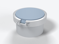
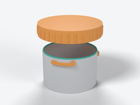
Reference lid: 200 × 150 mm, 700 mm gasket path, needs 1400–2800 N total (≈ 467 N per latch with 6 latches, 350 N with 8, at the high end). See required clamp force.
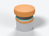
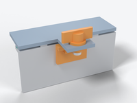
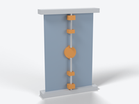
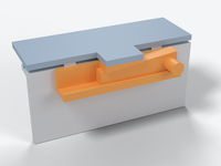
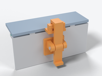
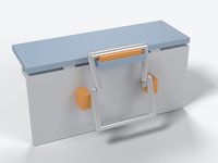
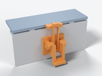
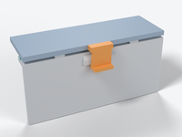
Calibration notes
Common basis used: sustained force = the lower of (a) the printed-structure capacity at the working allowables for ASA at 60-70 C (in-plane 3 / 4 / 5.5 MPa, pin bearing 6 / 8 / 10 MPa, across layers about 2 MPa, with stress-concentration factors where a reviewer applied them) and (b) the force a hand can deliver at about 20-50 N finger force or 3-4 N.m torque. Gasket set, creep and cold are reported as retention and are not subtracted, so a rigid latch's number is its as-set capacity and about 55-65 % of it remains after the first hot weeks (loss = set x k_latch/(k_latch + k_gasket), own calc). The Texin 985 gasket numbers (https://sushengpolymer.com/media/pdf/phFiH7_Texin-985.pdf) give 2.2x flexural modulus at -30 C, so a fixed-stroke latch sees up to 1.5-2x the force in the cold. The ASA hook anisotropy (lying 57 kg vs standing 17 kg, https://www.cnckitchen.com/blog/comparing-pla-petg-amp-asa-feat-prusament) and the M3 insert pull-out (about 1.17 kN, PETG, 23 C, short term, https://www.cnckitchen.com/blog/helicoils-threaded-insets-and-embedded-nuts-in-3d-prints-strength-amp-strength-assessment) are the only measured anchors. The hand-force and friction values come from https://elesa.com/en/elesab2bstoreca/Clamping-handles--Cam-levers--GN9272-A--d1. All other values are reviewers' or my own calculations. I found no printed sustained-load test for any mechanism, so every number is a calculation or estimate, and the ASA allowables themselves are an untested working rule, so expect +/-2x on absolute values (the ranking is more robust than the numbers). Where mounting choices differed between reviewers (4 mm pins vs M5 pins, thin wall vs thick boss), differences of about 20 % were left alone, and only larger or logically inconsistent gaps were adjusted. Peak values from the reviews (roughly 2.5-6x sustained) are room-temperature breaking estimates and were not used for the ranking. Two entries are closure-level, not per latch (perimeter band, threaded cap), and one is per latch point (multi-point rod). Material effects: PC (UV-stabilised grade only) could raise the structure-limited values about 1.3-1.5x (own judgement), but not the hand-limited or steel-limited ones. PETG and PETG-CF sit at their HDT at 60-70 C and are not suited to sustained load. PA6-CF loses about 22 % strength to moisture and should be avoided outdoors; PAHT-CF is acceptable but still creeps. Largest uncertainties: ASA hot creep allowables, anchor pull-out hot and sustained, printed-bead stiffness (+/-2x), and rim bending, since the latch count is limited by rim stiffness (about 28 mm pitch on a flat 3 mm edge, about 110 mm with a 20 mm skirt) before latch strength.
Adjustments made in calibration
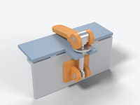
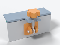
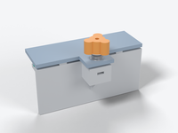
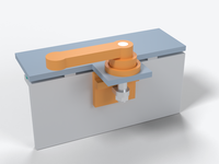
- swing-bolt-wing-nut · sustained_N.typical: 400 (reviewer; range 250-600) → 300 (range 200-450). The clevis must be a separate bracket anchored by screws or inserts into a 3-4 mm wall (the reviewer's own text says this has not been shown to carry 500 N hot), so it shares the baseline-screw anchor limit and adds a pin joint plus a slot seat across layers. It cannot exceed baseline-screws (250 N) by 1.6x. 300 N is the baseline scaled by about 1.2 for the larger M5 hardware, and it ranks below the cam lever, whose stud anchors in an M5 insert in a thick ledge.
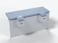
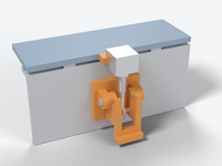
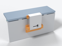
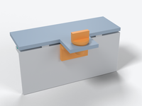
- wedge-slide-bolt · sustained_N.typical: 200 (reviewer; range 100-400) → 140 (range 75-280). Same hand-limited rule as the cap and bayonet: input at or near the 50 N comfort limit. The reviewer's own 1.64-2.48 push ratio gives 82-124 N from 50 N, so 200 N needs 80-125 N of push. The catch block is also a cantilever loaded across layers, as in the vise-action latch.
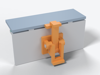
- double-throw-butterfly · sustained_N.typical: 85 (reviewer; range 45-150) → 65 (range 40-120). The reviewer deducted gasket set loss from a hand-limited closer, which the cap, bayonet and multi-point reviews did not do, so that deduction was inconsistent. The structural limit is the 10x5 mm hook arm with 1 mm of eccentricity (45-76 N at 3-5 MPa with Kt 1.5), the same hook-arm limit as the cam-hook (55 N) and bail (50 N). Typical set to the arm limit.
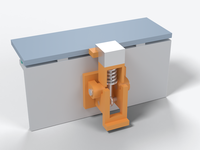
- oc-fixed-hook-pinned · sustained_N.typical: 110 (reviewer; range 70-150) → 85 (range 50-130). The analyst's neck check puts the load line 3 mm off the neck centre line on a straight beam. A real claw throat (inner radius about 2 mm, load line through the centre of curvature) gives about 0.10 MPa/N by the Winkler method used for the cam-hook and bail reviews, which is about 40-70 N at 4-7 MPa. The reviewer's 110 N credits an unmodelled bent-wire hook; set to a blend of the printed claw and the wire variant.
- perimeter-band-clamp · comparability basis: per latch → per closure (one T-bolt band, round or oval lid, about 377 mm path). The 800 N figure is the axial force of the whole band on a 120 mm round lid. Every other entry is per latch device on a rectangular lid. Value unchanged, but it is flagged as not directly comparable and excluded from the rectangular-lid recommendation.
- threaded-lid-cap · comparability basis: per latch → per closure (single round cap, 50 mm or less). One cap carries the whole 157 mm ring, and torque scales as diameter squared, so the figure does not extend to larger lids. Value unchanged (165 N); ranked on the number but not offered as a rectangular-lid latch.
Merged or excluded during the taxonomy step
- Steel over-center draw latches (Southco 97, Bossard BN 32753, Camloc, Ganter GN 850/851/853, Kipp K0080, Misumi, DE-STA-CO 331/341) — Not 3D-printable; used as force benchmarks only (Southco 97 135-670 N https://www.gripwell.com.sg/image/catalog/Gripwell/Furniture and Architectural Hardware/Latches/Draw Latches/97 Over-Center Draw Latch/Gripwell - 97 Over-Center Draw Latch.pdf ; Bossard 260-530 N https://www.bossard.com/pl-pl/eshop/zatrzaski-naciagowe/draw-latches-over-center-small-clamping-force-260-n-530-n-with-spring-loaded-anchor-plate-hole-for-wire-sealing/p/32753/ ; steel toggle latches 1.6-8.9 kN). Practical upgrade path is a bought stainless latch on printed bosses with through-bolts and metal backing washers, where the printed mount limits (~300-600 N, maker own est.).
- Hold-down / push-pull toggle clamps and printed F-clamp / cam F-clamp / toggle clamps (MakerWorld 2747558, 2616812, 2902106; Instructables linear toggle clamp) — Merged into the over-center and cam-lever entries. Same toggle principle, but the geometry needs space above the lid and is too bulky for the 70x35x30 mm envelope; none is designed around a gasket and none publishes a force. Steel ratings for scale only: Misumi hold-down 196-264 N stainless, 1000-2270 N steel; push-pull 910-3860 N (https://th.misumi-ec.com/en/vona2/detail/110310211769 , https://th.misumi-ec.com/en/vona2/detail/221005335113 ).
- Magnetic catch (printed carrier with neodymium magnet) — Dropped as a clamp: 30 N retaining (cabinet catch) to ~89 N (K&J 20 lb) pull at contact against thick steel, and a gasket gap cuts it sharply; 85A TPU needs several times more. Only useful as an alignment keeper or closure indicator (https://www.kjmagnetics.com/ml-l-y0-magnetic-latches-for-cabinets-doors-drawers ).
- Press-and-pull latch (Pelican Storm style) — Merged into snap-fit-compliant. Pelican designs it for an EPDM O-ring needing low closing force; no force published (PBT latch).
- Flexible elastomeric TPU/EPDM strap latch and compliant/bistable print-in-place snap lock — Merged into snap-fit-compliant. Elastic relaxation and compression set lose preload; 49-176 N new, snap-through tens of N.
- Sturdy print-in-place draw latch, print-in-place latch box, assembled printed draw latch, Pentair LXLATCH reprints — Merged into oc-fully-printed (same working principle and force class).
- Steel-pin-reinforced printed toggle latch (MakerWorld 1054989), engineered.at spoke-pin box, hook-and-catch / hasp printed hook — Merged into oc-fixed-hook-pinned and cam-hook-printed; the hook-and-catch is a load-path component, not a separate mechanism. Hook test numbers are kept as evidence.
- Engineered-plastic draw latches as separate entries (Southco E8, Southco 37 lever-assist) — Merged as commercial benchmarks into oc-adjustable-screw-hook and oc-fixed-hook-pinned (E8 is adjustable, 37 is fixed lever-assist).
- Fastener interfaces: heat-set inserts, direct self-tapping screws, captive nut pockets, Helicoil, integral printed threads, pin-through-lug, through-bolt clamping — Not mechanisms, but load interfaces. Folded into baseline-screws, swing-bolt-wing-nut, captive-screw-spring-stack and threaded-lid-cap as evidence (Helicoil gave no advantage over screw-in-plastic in PETG: 120 vs 118 kg).
- Gasket-side measures: positive compression stops, adjustable preload, compliant element in series, rib-into-flat gasket, solid bead, narrow rib, hollow gasket, round cord, tongue-and-groove gland, stiffened rim — Not latches. Used in gasket_brief and required_force and as design requirements on the latches (hard stop beside each latch, adjustability or series spring, stiff rim). Note the internal tension that the gasket researcher's 2-4 N/mm target and 20-25 % squeeze only coincide for a narrow ~1.2 mm rib.
- Design practices: metal-pin load path, added joint compliance (longer thinner fastener), re-tension after bedding-in, metal insert for mounting screws, ASA hardware selection — Practices, not mechanisms; merged into the relevant entries and materials_brief.
- Epoxy-bonded latch casing test (UW Midsun) and Blue Robotics clip anecdote as stand-alone items — The epoxy test measures the adhesive bond (PETG 82 lb), not the latch; the clip anecdote is merged into perimeter-band-clamp.
- Rotary claw-and-striker latch and ratchet pull-in latch as stand-alone entries — Completeness gap I could not close. The web-search budget was exhausted when I tried to source them (all five completeness searches were refused), and Southco's rotary-latch page returned HTTP 403. The ratchet-stop and stored-energy variants are covered through the ITW patents inside oc-spring-loaded-compensating; the claw-and-striker latch needs a follow-up search before it can be ranked. Likewise no search could be run for wedge latches, so wedge-slide-bolt rests on reasoning only.
- Unsupported source claims removed — The Firgelli toggle-latch page does not give the 1/(2 tan) gain or support 'clamp force = stretch x spring rate' (it says real force depends on geometry and stiffness) and does not mention wedges; the toggle gain is therefore labelled my own calculation. The Penn Elcom page does not say 'double-throw'. The Texin sheet and Elesa GN 927.2 table were verified directly.