20 mechanisms · TPU 85A seal · outdoors
Printable Enclosure Latches
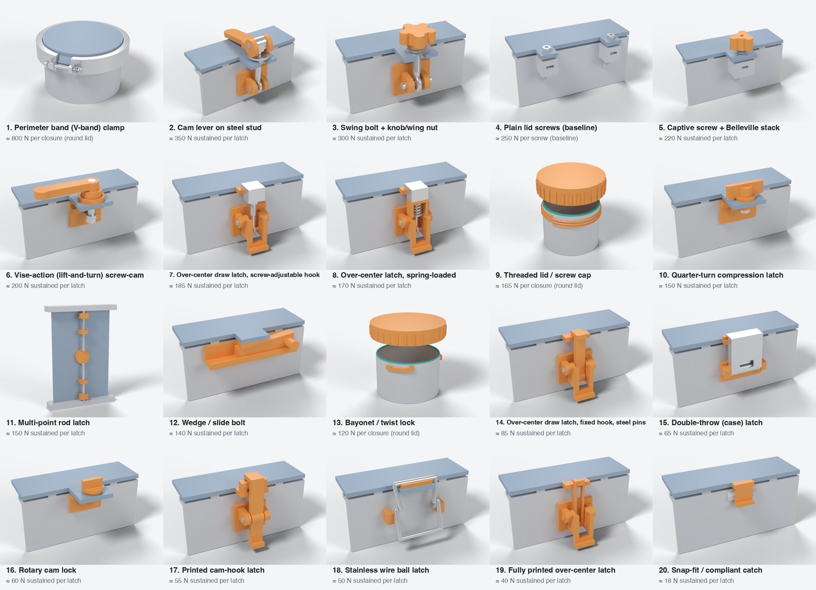
Which 3D-printable latch can hold the most clamp force on a TPU 85A gasket in an outdoor enclosure? This project ranks 20 mechanisms by the force one latch can hold for months in hot sun, and explains how to build a sealing closure around the winner.
Bottom line. No all-plastic latch holds enough force for an 85A seal. The winners are printed levers and brackets that put the preload into stainless steel (a stud, bolt or screw) and back it with a spring stack. Best overall: an eccentric cam lever on a steel stud (≈ 350 N per latch). Runners-up: a swing bolt with a knob (≈ 300 N) and a captive screw with a Belleville stack (≈ 220 N). Use 6–8 of them on a stiff rim, a narrow 1.2–1.6 mm TPU rib, and a printed hard stop next to every latch.
The three to start with
The best balance of force, preload kept after hot sun, a hard stop and printability. Each page has the 3D model, parts list, print files and the full analysis.
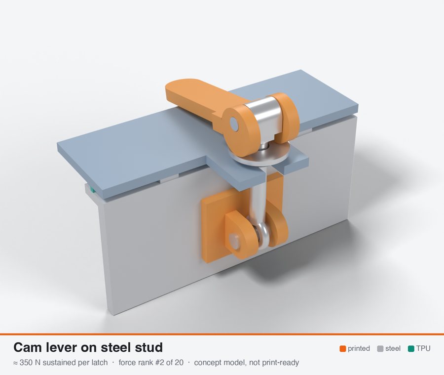
Cam lever on steel stud
Highest true per-latch force. Limits are the M5 pin bearing in 2x7 mm ears and the insert anchor in a thick ledge. A steel stud, plate and spring stack are mandatory, so it is a hybrid with a printed lever and bracket. Adjustable, with a positive stop and about 25 N hand force.
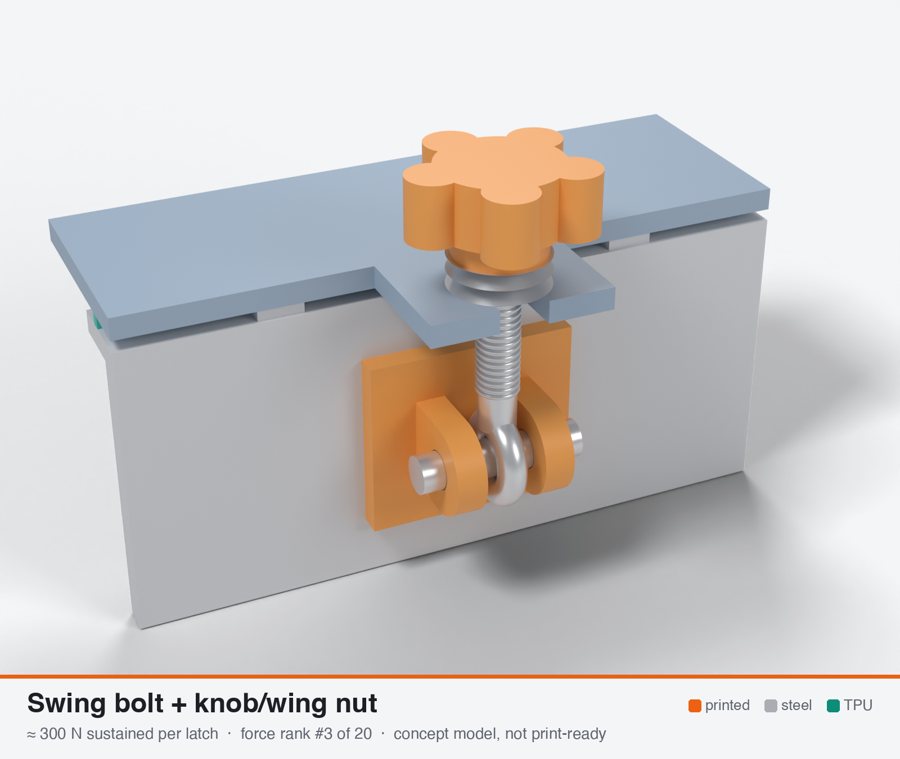
Swing bolt + knob/wing nut
Cut from 400 N because the clevis bracket anchors to the wall like a baseline screw and adds a pin joint. Torque is set by the hand, so a Belleville stack or torque-limiting knob is needed. Fully re-tensionable, but slow to operate.
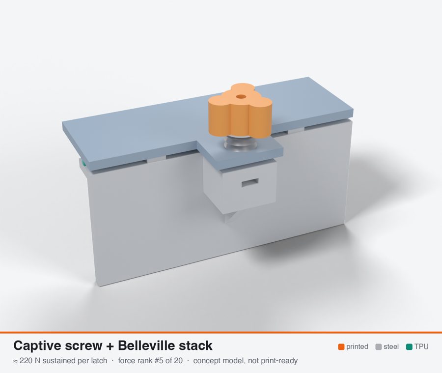
Captive screw + Belleville stack
Same boss limit as the baseline, slightly lower because a spring holds the load continuously. Best retention of the screw types (calculated about 85-95 % held after hot set, not validated) and removes most of the cold overload. Needs a die spring or Belleville stack, not a small coil.
How much each latch holds
Sustained clamp force per latch on a rectangular lid: what it keeps holding for months at 60–70 °C, not its breaking load. The reference lid needs 1.4–2.8 kN in total.
-
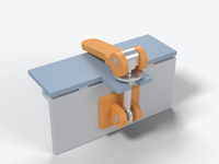 Cam lever on steel stud220–550 N · 4–8 latches
350 N
-
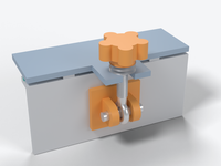 Swing bolt + knob/wing nut200–450 N · 5–10 latches
300 N
-
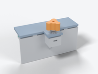 Captive screw + Belleville stack110–380 N · 7–13 latches
220 N
-
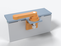 Vise-action (lift-and-turn) screw-cam100–350 N · 7–14 latches
200 N
-
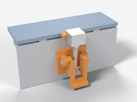 Over-center draw latch, screw-adjustable hook130–240 N · 8–16 latches
185 N
-
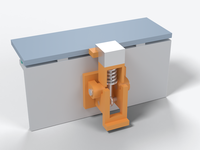 Over-center latch, spring-loaded120–220 N · 9–17 latches
170 N
-
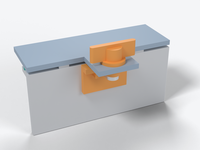 Quarter-turn compression latch60–300 N · 10–19 latches
150 N
-
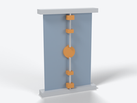 Multi-point rod latch60–300 N · 10–19 latches
150 N
-
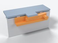 Wedge / slide bolt75–280 N · 10–20 latches
140 N
-
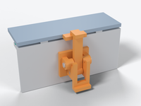 Over-center draw latch, fixed hook, steel pins50–130 N · 17–33 latches
85 N
-
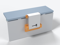 Double-throw (case) latch40–120 N · 22–44 latches
65 N
-
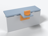 Rotary cam lock25–100 N · 24–47 latches
60 N
-
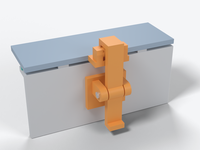 Printed cam-hook latch25–100 N · 26–51 latches
55 N
-
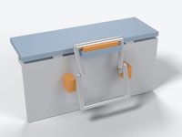 Stainless wire bail latch20–90 N · 28–56 latches
50 N
-
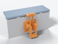 Fully printed over-center latch15–65 N · 35–70 latches
40 N
-
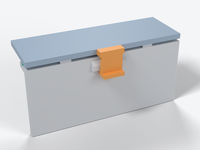 Snap-fit / compliant catch8–40 N · 78–156 latches
18 N
sustained force, newtons per latchrangea plain M5 screw into the box: 250 N, the number to beat
Top 10 latches by sustained clamp force
Per latch, on a rectangular lid, printed in ASA, at 60–70 °C surface temperature, safety factor ≈ 2 on long-term strength. "Sustained" means the force it keeps holding for months. It is not the breaking load.
| # | Preview | Mechanism | Sustained clamp force per latch | Range | Latches for the reference lid¹ | Adjustable | Built-in stop | Seal fit | Outdoor | Build |
|---|---|---|---|---|---|---|---|---|---|---|
| 1 | |
Cam lever on steel stud | 350 N | 220–550 N | 4–8 | yes | yes | 7/10 | 7/10 | Printed + steel hardware |
| 2 | |
Swing bolt + knob/wing nut | 300 N | 200–450 N | 5–10 | yes | no | 7/10 | 7/10 | Printed + steel hardware |
| 3 | |
Captive screw + Belleville stack | 220 N | 110–380 N | 7–13 | yes | no | 8/10 | 7/10 | Printed + steel hardware |
| 4 | |
Vise-action (lift-and-turn) screw-cam | 200 N | 100–350 N | 7–14 | yes | yes | 6/10 | 6/10 | Mostly hardware |
| 5 | |
Over-center draw latch, screw-adjustable hook | 185 N | 130–240 N | 8–16 | yes | no | 6/10 | 6/10 | Printed + steel hardware |
| 6 | |
Over-center latch, spring-loaded | 170 N | 120–220 N | 9–17 | yes | no | 8/10 | 5/10 | Printed + steel hardware |
| 7 | |
Quarter-turn compression latch | 150 N | 60–300 N | 10–19 | yes | yes | 5/10 | 5/10 | Printed + steel hardware |
| 8 | |
Multi-point rod latch | 150 N | 60–300 N | 10–19 | yes | no | 4/10 | 5/10 | Mostly hardware |
| 9 | |
Wedge / slide bolt | 140 N | 75–280 N | 10–20 | yes | yes | 6/10 | 5/10 | Fully printed |
| 10 | |
Over-center draw latch, fixed hook, steel pins | 85 N | 50–130 N | 17–33 | no | no | 3/10 | 6/10 | Printed + steel hardware |
Why each one lands where it does
- Cam lever on steel stud — Highest true per-latch force. Limits are the M5 pin bearing in 2x7 mm ears and the insert anchor in a thick ledge. A steel stud, plate and spring stack are mandatory, so it is a hybrid with a printed lever and bracket. Adjustable, with a positive stop and about 25 N hand force.
- Swing bolt + knob/wing nut — Cut from 400 N because the clevis bracket anchors to the wall like a baseline screw and adds a pin joint. Torque is set by the hand, so a Belleville stack or torque-limiting knob is needed. Fully re-tensionable, but slow to operate.
- Captive screw + Belleville stack — Same boss limit as the baseline, slightly lower because a spring holds the load continuously. Best retention of the screw types (calculated about 85-95 % held after hot set, not validated) and removes most of the cold overload. Needs a die spring or Belleville stack, not a small coil.
- Vise-action (lift-and-turn) screw-cam — Limited by the keeper ledge loaded across layers (120-240 N). Adjustable, with a positive stop and about 22 N hand force. Printed helical ramps wear. Force scatter is about 40 % without a spring.
- Over-center draw latch, screw-adjustable hook — Over-center lever with a steel eye-bolt adjuster. About five printed failure modes (wall bearing, pin bores, lug, ear root, keeper) sit within about 1.4x of each other. Re-tensionable (0.2 turn restores hot-set loss) and quick to operate. A rigid link, so scheduled re-tensioning is required.
- Over-center latch, spring-loaded — Same printed limits as the screw-hook version, minus a knock-down for the carriage and guides. Best end-of-life retention of the over-center types (about 92 % kept). Fit in the envelope is unproven, and the exposed spring and guide are weak outdoors.
- Quarter-turn compression latch — A printed pawl alone gives about 115 N. 150-350 N needs a steel pawl and a keeper. Commercial 4-6 mm ramp travel does not match the 0.5 mm gasket stroke, so force scatter is about 40 %. Better with foam or a thin rib than with the 85A design rib.
- Multi-point rod latch — This is per latch POINT on a 4-point door. One handle delivers only about 0.57-0.8 kN in total before set loss, which is 0.5-1.1 N/mm. It does not fit the envelope. Rod, bellcrank and guide complexity outdoors hurts durability.
- Wedge / slide bolt — Cut from 200 N to the force a reasonable push can deliver. The wedge gives excellent stroke control (10:1) and recovers hot set, but it needs a separate pivoted tab or catch block anchor. Loose wedge, fretting and ice jams are the risks.
- Over-center draw latch, fixed hook, steel pins — Cut from 110 N. The printed claw throat is a curved-beam limit of about 40-70 N, with a bent A4 wire hook the only route to 100 N or more. No adjustment, so +/-0.3 mm of tolerance is +/-160 N. After hot set the line load falls to about 1 N/mm or less.
Below the top 10 (not recommended as the clamp for an 85A seal): Double-throw (case) latch 65 N, Rotary cam lock 60 N, Printed cam-hook latch 55 N, Stainless wire bail latch 50 N, Fully printed over-center latch 40 N, Snap-fit / compliant catch 18 N.
¹ Number of latches needed on the reference lid: 200 × 150 mm, 700 mm gasket path, 1.4–2.8 kN total for the recommended TPU rib (required clamp force). Rim stiffness usually forces at least about 7 latches anyway: the pitch is about 110 mm with a 20 mm skirt and only about 28 mm on a flat 3 mm lid edge.
Round lids, and the baseline to beat
These closures can't be compared one-to-one with the latches above. A band clamp or a threaded cap clamps the whole lid at once, and it only works on a round lid.
| Preview | Closure | Sustained clamp force | Range | Note |
|---|---|---|---|---|
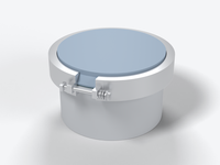 |
Perimeter band (V-band) clamp | 800 N | 400–1400 N | per closure, round/oval lid |
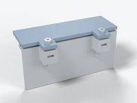 |
Plain lid screws (baseline) | 250 N | 120–400 N | per screw; the number to beat |
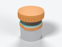 |
Threaded lid / screw cap | 165 N | 90–400 N | per closure, round/oval lid |
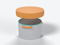 |
Bayonet / twist lock | 120 N | 50–180 N | per closure, round/oval lid |
On a round lid of about 100–200 mm, a stainless V-band with a printed flange ring and a spring in the T-bolt is the strongest option found. It gives an even line load all the way round, so rim bending stops being a problem.
Website: everything here is also at latches.nclr.eu: a page for each mechanism with its 3D model, parts, print files and the full analysis, plus the 3D gallery, the interactive explorers, the shopping list and the research notes.
Models, videos and explorers
Every mechanism has a concept model at real scale. Rotate them, watch the five strongest latches open and close with the clamp force shown live, or drag the numbers in two interactive explorers.
3D gallery
All 20 models in the browser with their numbers. Click a part to see where it sits, hide the lid, play the five animations.
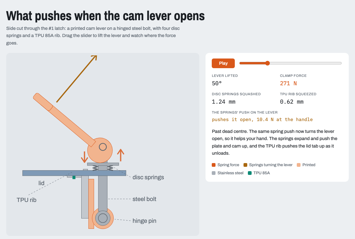
What pushes when it opens
Lift the lever with a slider and see the spring force, the seal squeeze and which way the springs turn the lever.
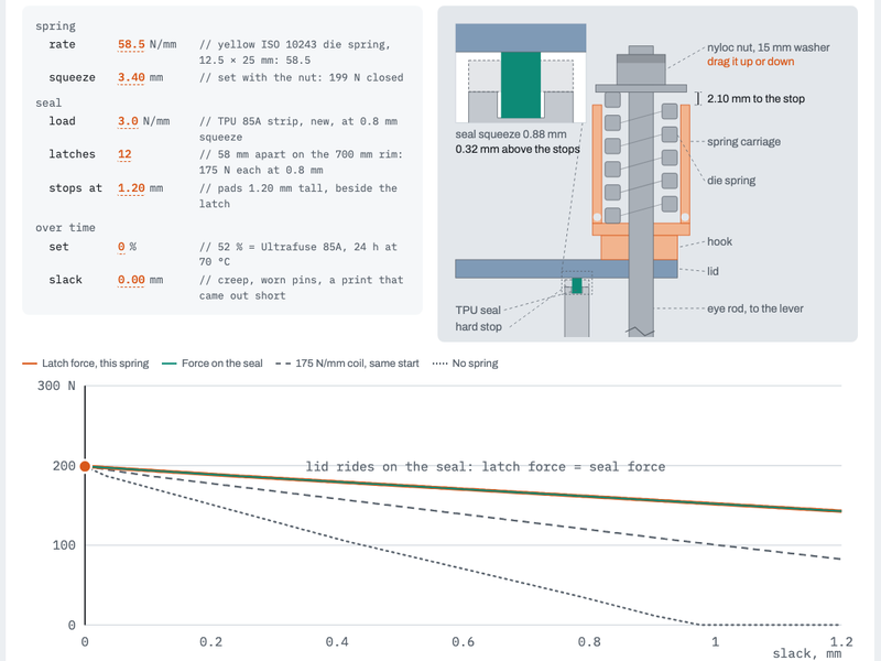
How the spring holds it shut
Drag the spring rate, the nut setting, the seal load, the stops, seal set and slack, and see the latch force, the seal pressure and the work to close.
The five strongest latches, opening and closing
Best picks for the actual goal: a sealed outdoor enclosure
This ranking weighs clamp force against preload retention after hot sun, a positive compression stop, outdoor durability and printability.
- Cam lever on steel stud (350 N) — Highest sustained force of any per-latch mechanism that stays adjustable (about 350 N, range 220-550). With 6-8 latches this covers the 1.4-2.8 kN window, and it has a positive stop, a steel stud and plate, and low hand effort (about 25 N). It must have a Belleville or spring stack under the setting nut (about 4x softer than the gasket) to cut 85A set loss from 30-58 % to about 10 % and to cap the cold overload. Also needs an A4 stud, pin and plate, and a stiffened rim. Confidence low; 1-week 65 C force-gauge soak required.
- Swing bolt + knob/wing nut (300 N) — About 300 N sustained (range 200-450). A steel eye-bolt with a washer or Belleville stack gives the highest force among the fully recoverable closures, and it can be re-tightened after the first hot week. Use an A2/A4 DIN 444 bolt, not the zinc 4.6 version. Print the clevis flat as a separate bracket, because an integral upright clevis tears at about 340 N or less. Limit torque with a small knob or slip clutch. Usability 4 (several turns each).
- Captive screw + Belleville stack (220 N) — About 220 N (range 110-380) on the simplest printed geometry (boss, insert, washer). The spring stack gives the best calculated retention (about 83-96 % after hot set, unvalidated) and avoids the +100 % cold overload of a rigid screw. Add a printed or steel-sleeve hard stop. Needs a die spring or Belleville stack, since a coil spring light enough to help is impractical. About 11 mm thread depth; usability 4.
- Over-center draw latch, screw-adjustable hook (185 N) — About 185 N (range 130-240) with the best operability of the lever types (about 10 N hand force, one motion). A steel eye-bolt re-tensions (about 0.2 turn restores a 37 % hot-set loss). Six to eight latches give about 1.9-2.6 N/mm, the bottom of the design window. Rigid, so expect to re-tension after the first hot weeks. Fit a locknut and a printed hard stop.
- Over-center latch, spring-loaded (170 N) — About 170 N (range 120-220), but it keeps about 92 % of its preload after hot set (rigid latches keep about 63 %) and the cold rise is only about 10 %. Needs 8 or more latches to reach the lower window edge. Printability 6, exposed spring and sliding carriage lower durability to 5, and fit in 70x35x30 mm is not demonstrated. A steel stop is needed so the spring cannot coil-bind.
The full list of 10 is in the full ranking and in data/ranking.csv.
What each one is made of: every mechanism page has a parts list, covering what to print, what to buy (with sizes) and what is printed into the box or lid. Threaded anchors are M3 square nuts in printed slots, not heat-set inserts. All 20 lists are on one page in docs/parts.md.
Print files: every mechanism has print-ready STL files in print/, already turned the way they go on the bed, with a STEP file for CAD. Most latches are printed parts plus a few bought steel parts (pins, eye bolts, springs, screws). The threaded cap, the bayonet, the snap fit and the fully printed draw latch need nothing but screws and the TPU seal. Parts that go on the box or lid come as short test coupons of box wall and lid, so you can try a latch before building it into your enclosure. Clearances and print settings: print/README.md.
What to buy: the shopping list has every bought part with an example link, mostly at Grobotronics (Mouser for a few), and the Greek name to ask for at a hardware store where none of them stocks it. Each mechanism's parts list links the same items. In the 3D gallery you can click a part to highlight it on the model. The pages for the five strongest latches walk through how to assemble them, step by step, including how to set the clamp force: cam lever, swing bolt, captive screw, lift-and-turn latch and over-centre draw latch.
What matters more than the latch
- Pick the gasket to match the latches. A solid 3 × 3 mm TPU 85A bead needs 6.5–11.6 kN at 15–25 % squeeze on the reference lid. That is over 1 kN per latch, which no printed latch holds for months. A 1.2–1.6 mm wide, ≥ 2 mm tall rib at 20–25 % squeeze needs only 2–4 N/mm. Print it flat at 100 % infill and seal it against an ironed land.
- Put a hard stop next to every latch. The gasket only compresses 0.2–0.75 mm, which is about the same as FDM warp and hinge play. A printed stop at about 0.75–0.8 × the free rib height sets the squeeze. The latch then only has to hold the lid on the stop.
- Put a spring in series. At 70 °C, printed 85A TPU takes about 52 % compression set. A rigid latch therefore loses 30–58 % of its force after the first hot weeks. A Belleville or stainless spring stack about 4× softer than the gasket cuts that loss to about 7–10 %. It also absorbs the cold case: the gasket is 2.2× stiffer at −30 °C.
- Stiffen the rim before buying a stronger latch. Latch spacing is limited by how much the lid edge bends between latches, not by latch strength. Spacing is about 28 mm on a flat 3 mm edge, about 110 mm with a 20 mm skirt and about 154 mm with a 30 mm box rim.
- Material: ASA by default, UV-stabilised PC for more margin. PETG and PETG-CF reach their HDT (≈ 68 °C) in a black box in the sun, so don't use them for loaded parts. PA6-CF absorbs water and creeps. Use A2/A4 stainless for every pin, screw and spring.
- Orientation. Keep lever, link and hook loads in the XY plane, with pin axes along Z. An ASA hook printed standing held 17 kg, against 57 kg printed lying (CNC Kitchen). That is 29 % of the strength.
Details: required clamp force · outdoor materials
How much to trust these numbers
- The research found no sustained-load test of any printed latch. Every force here is an engineering calculation built on a few measured anchors: CNC Kitchen hook and insert tests, the Texin 985 TPU compression curve, and Elesa cam-lever tables. Treat absolute values as ±2×. The order of the ranking is more reliable than the numbers.
- Each number was computed by an analyst agent, then recomputed by an independent adversarial reviewer. The reviewer corrected 17 of 20 numbers, every one of them downward. A final calibration pass then aligned the assumptions across mechanism families.
- The session's web-search budget ran out partway through the analysis. The later agents relied on direct page fetches and calculation. See the limitations.
- Before you trust a design, test it: measure the closing force with a force gauge, soak the closed enclosure at 65 °C for a week, then measure again.
How this was researched
The research ran as a multi-agent workflow (workflow/latch-research.workflow.js) with 17 agents and about 930 web/tool calls:
- Sweep: 5 specialist researchers worked in parallel: industrial latch catalogs, maker designs, measured test data, gasket engineering, and outdoor materials.
- Taxonomy: a lead engineer merged their 79 raw entries into 20 distinct mechanisms, filled gaps and derived the required gasket force.
- Analyze: mechanical-engineer agents produced a worked clamp-force calculation for each mechanism family.
- Verify: an adversarial reviewer for each family recomputed every number from first principles and checked the cited sources.
- Calibrate: a chief-engineer agent made the assumptions consistent across families and produced both rankings.
More detail, the agent roles and the limitations are in docs/methodology.md.