No. 02 of 20 · Rectangular lids
Cam lever on steel stud
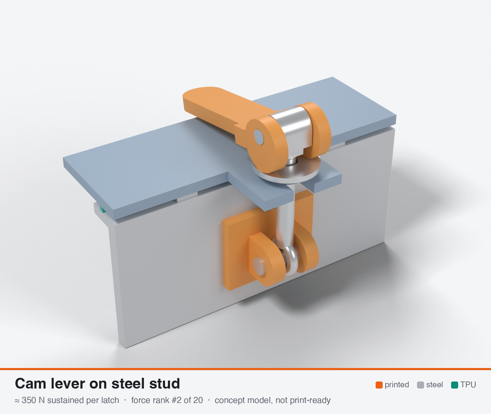
Eccentric cam clamping lever on a steel stud with steel contact plate
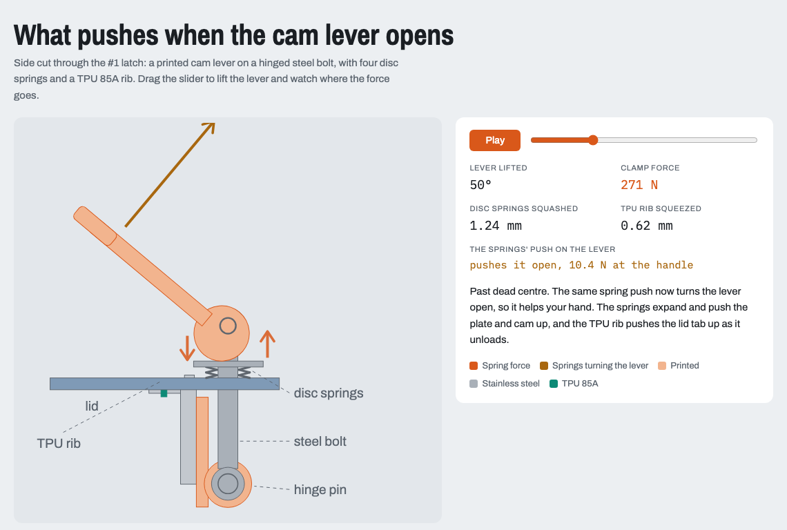
Model note: The 3D model hinges the steel bolt on a pin at its bottom (an eye bolt in the bracket) and puts the adjustment in a threaded head under the lever. The research version screws the stud solid into the bracket, which would leave the bolt trapped in the lid slot so the lid could never come off.
- Force rank
- 2 of 20
- Rank for outdoor sealing
- 1
- Latches for the reference lid
- 4–8
- Build
- Printed + steel hardware
- Hand force to close
- ≈ 23 N
- Adjustable preload
- yes
- Positive compression stop
- yes
- Force basis
- calculated
- Review verdict
- corrected
- Confidence
- low
Verdict: Highest true per-latch force. Limits are the M5 pin bearing in 2x7 mm ears and the insert anchor in a thick ledge. A steel stud, plate and spring stack are mandatory, so it is a hybrid with a printed lever and bracket. Adjustable, with a positive stop and about 25 N hand force.
Why it ranks #1 for sealing: Highest sustained force of any per-latch mechanism that stays adjustable (about 350 N, range 220-550). With 6-8 latches this covers the 1.4-2.8 kN window, and it has a positive stop, a steel stud and plate, and low hand effort (about 25 N). It must have a Belleville or spring stack under the setting nut (about 4x softer than the gasket) to cut 85A set loss from 30-58 % to about 10 % and to cap the cold overload. Also needs an A4 stud, pin and plate, and a stiffened rim. Confidence low; 1-week 65 C force-gauge soak required.
On this page
Parts
Per latch: 2 parts to print, 9 items to buy, 3 features printed into the box or lid and the TPU 85A seal. Parts marked † are not drawn in the 3D model. In the 3D gallery you can click a part to see where it sits. The last column links the print file, or an example of the part in a shop (see the shopping list).
| Part | Qty | Type | What to use | File or shop |
|---|---|---|---|---|
| Hinge bracket | 1 | ASA, flat on its back; ears 7 mm thick, 5.2 mm hinge bore | bracket.stl | |
| Cam lever | 1 | ASA, on its side (pin axis vertical) with supports under the upper disc, 100 % infill; 4.2 mm bore | cam-lever.stl | |
| Bracket screws † | 4 | Buy | M3 × 10 A2/A4 socket screws (DIN 912) | Grobotronics |
| Square nuts † | 4 | Buy | M3 square nuts (DIN 562), dropped down the channels in the box wall | Grobotronics |
| Hinge bolt | 1 | Buy | M5 × 30 stainless screw with an M5 nyloc nut, through the bracket ears and the eye | M5 screw · M5 nyloc |
| Eye bolt | 1 | Buy | M5 × 50 A2/A4 eye bolt (DIN 444); the eye at most 12 mm across and 6.5 mm thick | Schraubenhandel24 |
| Disc springs | 4 | Buy | Stainless disc springs for M5 (DIN 2093, 10 × 5.2 mm), stacked in series | RVS Edelstahl |
| Contact plate | 1 | Buy | Stainless washer 15–18 mm across (DIN 9021 or DIN 440 for M5), or a 1.5–2 mm steel plate; the cam rolls on it | Inox Store |
| Fork head | 1 | Buy | M5 × 15 hex standoff, female both ends (8 mm across flats), or a coupling nut; cross-drilled 4.2 mm, 3 mm from one end, for the lever bolt | Grobotronics |
| Jam nut | 1 | Buy | M5 A2/A4 nut (DIN 934); locks the fork head, whose height sets the clamp force | Grobotronics |
| Lever bolt | 1 | Buy | M4 × 20 stainless screw with an M4 nyloc nut; the lever turns on it | M4 screw · M4 nyloc |
| Slotted lid tab | 1 | Printed with the lid | Slot 6.4 mm wide, open at the end; flat seat for the springs | lid-coupon.stl |
| Hard stops | 2 | Printed with the box | Pads on the rim either side of the latch, 1.6 mm tall: 0.8 mm below the free seal | box-coupon.stl |
| Nut channels | 4 | Printed with the box | Inside pillar with a 5.7 × 2.0 mm channel per nut, open on the rim outside the seal; blind 3.4 mm screw holes, so no path into the box | box-coupon.stl |
| Seal strip | 1 | Seal (TPU 85A) | TPU 85A, 1.5 × 3.4 mm, in a 1.8 × 1.0 mm groove in the rim; the latch squeezes it 0.8 mm | seal-strip.stl |
Print files
Download all print files for this latch (ZIP, 0.1 MB)
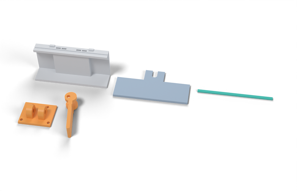
Print version: The fork head is an M5 hex standoff cross-drilled for an M4 bolt, the hinge pin an M5 screw with a nyloc nut. The bracket ears are 7 mm thick and the cam discs are joined to the handle by a web in each disc's plane.
Print in ASA (TPU 85A for the seal), 0.2 mm layers, at least 4 walls; settings and the clearances used are in print/README.md. The parts are already turned the right way up for printing. The box and lid coupons are short test sections with this latch's box-side and lid-side features, so you can try the latch before building it into your own enclosure.
| File | Material | Qty | Size (mm) | How to print |
|---|---|---|---|---|
| bracket.stl | ASA | 1 | 38 × 31 × 16 | Flat on its back, no supports. 4 × M3 × 10 into the box; ears 7 mm thick; 5.2 mm hinge bore for an M5 × 30 screw with a nyloc nut. |
| cam-lever.stl | ASA | 1 | 17 × 54.3 × 16.8 | On its side (pin axis vertical) so the cam rim is smooth perimeters; supports under the upper cam disc; 100 % infill. 4.2 mm bore for an M4 × 20 bolt with a nyloc nut. |
| box-coupon.stl | ASA | 1 | 90 × 24 × 41.6 | Upright, no supports. A section of box wall with this latch's box-side features: seal groove, hard stops, and an inside pillar with nut channels. Push an M3 square nut down each of the 4 channels in the rim before fitting the screws. Copy these features into your own box. |
| lid-coupon.stl | ASA | 1 | 90 × 47 × 3 | Flat, top up. A section of lid with this latch's lid-side features. Copy them into your own lid. |
| seal-strip.stl | TPU 85A | 1 | 90 × 3.4 × 1.5 | TPU 85A, 100 % infill, lying on its side. Press it into the rim groove: it stands 2.4 mm proud and the latch squeezes it 0.8 mm, until the lid lands on the hard stops. |
All printed parts in their assembled positions, for CAD: cam-lever-steel-stud.step.
How to assemble
This follows the print files and the parts list above. They are first prototypes, so do one test assembly, on the box and lid coupons, before printing a full set.
Tools: 2.5, 3 and 4 mm hex keys, 7 and 8 mm spanners (M4 and M5 nuts), a 4.2 mm drill, calipers and a feeler gauge.
1. Print and prepare
- Print
bracket.stlandcam-lever.stlin ASA as they come (the lever on its side, with supports under the upper cam disc and 100 % infill). - Print the box with the two hard stops beside the latch, and the lid with its slotted tab, or the box and lid coupons to try it first.
- Where the bracket goes, the box wall needs an inside pillar 10 mm thick with a 5.7 × 2.0 mm channel for each of the 4 M3 square nuts. The channels drop in from the rim, between the seal and the outside, and the screw holes stop inside the wall. A nut slot that opens into the box would let water in along the screw thread. The box coupon shows the layout.
- Run a 5.2 mm drill through the bracket's hinge bore and a 4.2 mm drill through the lever bore if they are tight.
- Cross-drill the M5 × 15 hex standoff (the fork head) 4.2 mm, 3 mm from one end, square to two of its flats.
- Check the lid on the bare box: it should rest on the TPU rib with about a 0.8 mm gap above the hard stops. If it already touches the stops, the rib is too low and won't seal.
2. Bracket and hinge
- Drop the 4 M3 square nuts down their channels from the rim. They land level with the screw holes.
- Put the eye of the M5 eye bolt between the bracket's two ears. Push the M5 × 30 hinge bolt through and fit the nyloc nut, just snug so the bolt still swings.
- Screw the bracket to the box with the 4 M3 × 10 screws, snug but not hard: the nuts sit in plastic. In the model the hinge pin sits 9 mm out from the wall and about 24 mm below the underside of the lid tab.
- Check that the bolt stands upright in the middle of the tab's slot and swings about 35° outward without rubbing.
3. The stack on the bolt
It's easiest with the bolt swung out. From the bottom up:
- 4 disc springs, alternating so each pair touches rim to rim or hole to hole (side view:
> < > <). That's what "in series" means. - The steel contact plate.
- The M5 jam nut, a few turns on, left loose for now.
- The fork head (the cross-drilled standoff), screwed on a few turns, cross hole at the top.
- The cam lever. Its two cam discs go either side of the fork head; push the M4 × 20 lever bolt through and fit the nyloc nut, just snug so the lever turns freely. The pin hole sits off-centre in the cam: when the lever lies down over the lid, the thicker side of the cam must face down onto the plate.
4. Set the clamp force
Before fitting the springs, measure the 4-spring stack with calipers twice: free, and pressed flat in the calipers' jaws. Your target is the flat height plus a quarter of the difference, about three-quarters of the way to flat. For four 10 × 5.2 × 0.4 mm springs that's about 0.8–0.9 mm shorter than free; never set them flat, or nothing is left to make up for the seal creeping.
- Close the lid on the box, swing the bolt into the slot and lower the lever.
- Screw the fork head up until the lever closes with no resistance. Then screw it down until the lever just starts to resist at the end of its travel. That's zero.
- From zero, screw it down about 2 more full turns (1.6 mm on M5): 0.8 mm goes into the rib, the rest into the springs. To turn the fork head, lift the lever, take out the lever bolt and turn the fork in half turns (0.4 mm). Then refit the bolt.
- Check with the latch closed:
- The lid sits on the hard stops: a 0.05 mm feeler gauge won't go in.
- The spring stack is at the target height (calipers across it).
- Closing takes about 25 N at the handle, a firm push like a stapler. Much harder means you've gone too far: back off half a turn.
- A half turn is a big step on a stack this short. For finer steps, add a 0.2 mm stainless shim under the springs.
- Tighten the jam nut up against the fork head.
5. Final checks
- Open and close a few times. The lever should click over dead centre and rest on the lid, which is its stop, and the bolt should swing freely in and out of the slot.
- Fit every latch on the lid the same way; the reference lid needs 4–8. Close them in a cross pattern, opposite sides in turn, so the lid seats evenly.
- After the first hot week, check the spring stack height again. If the seal has set and the stack has grown, tighten the fork head half a turn.
How it works
A printed lever with an eccentric cam pivots on a steel pin that passes through the eye of a steel stud. Swinging the lever 90-180 degrees makes the cam bear on a hardened washer or contact plate on the lid. The stud is pulled by the cam throw and clamps the lid. A fine-thread setting nut sets the preload and the cam end position. The clamp stays on after release because the cam reaches an over-center or friction-locked position.
Mechanical advantage
About 19-21:1, taken from the manufacturer force table for steel GN 927.2: 75 N gives 1,450 N (19.3:1, 33 mm arm), 125 N gives 2,600 N (20.8:1, 47 mm), 200 N gives 4,300 N (21.5:1, 62 mm), 350 N gives 7,000 N (20.0:1, 76 mm). Printed version with a 50 mm lever and 2.5 mm effective cam offset (friction included) gives about 20:1. A cam throw of e = 2 mm gives about 3-4 mm of stud travel over 180 degrees, far more than the 0.2-0.75 mm the gasket needs, so a series spring fits in the stroke.
What limits the force
Bearing of the steel pivot pin in the printed lever ears (4-5 mm pin, 2 x 6-8 mm ears, about 8-10 MPa sustained). Next: the printed cam face (flat-spots unless a steel plate or insert is used) and the stud anchor in the base (insert pull-out or Z-direction load across layers). Steel stud and pin are never the limit: class 8.8 M5 proof load is 8.2 kN.
Analyst's calculation
Analyst's sustained estimate: 300–700 N, typical 450 N; peak 1400 N.
NO PRINTED CAM-LEVER TEST EXISTS in anything I could reach; the web-search tool refused new searches (budget exhausted). The steel path is verified from the manufacturer table; the printed limits are my own calculation. STEEL REFERENCE (fetched and confirmed by me): GN 927.2 table 75/125/200/350 N hand force gives 1,450/2,600/4,300/7,000 N; recommended safety factors 1.2-1.5 static, 1.8-2.4 pulsating, 3-4 alternating; friction coefficients plastic/steel 0.15, plastic/plastic 0.25, steel/steel 0.2 (https://elesa.com/en/elesab2bstoreca/Clamping-handles--Cam-levers--GN9272-A--d1). GN 927.7 family reaches 8 kN and type A has an adjustable contact plate set by a fine-thread knurled nut (https://ctemag.com/?p=107957, fetched and confirmed). PRINTED PIVOT BEARING (own calc, ASA, working rule 8-10 MPa): M4 pin, 2 ears x 6 mm: 4 x 12 = 48 mm2 gives 384-480 N. M5 pin, 2 x 8 mm: 5 x 16 = 80 mm2 gives 640-800 N. EAR NET SECTION (14 mm boss, 5 mm hole, 2 x 8 mm ears, in-plane XY load): 144 mm2, so 4.9 MPa at 700 N, at the 3-5 MPa cautious limit. CAM FACE: Hertz line contact between printed cam (R = 9 mm, 12 mm wide, E* about 2 GPa) and a flat steel plate gives 42 / 54 / 64 MPa peak at 300 / 500 / 700 N. That is far above the 8-10 MPa sustained limit, so a bare printed cam will flat-spot and creep. Use a steel contact plate and a steel cam insert or dowel. ANCHOR: stud threads into an M5 heat-set insert in a thick base ledge. Insert pull-out is 119 kg (about 1.17 kN) for M3 in PETG at room temperature, short term, in flat 4-perimeter 100 % infill coupons (https://www.cnckitchen.com/blog/helicoils-threaded-insets-and-embedded-nuts-in-3d-prints-strength-amp-strength-assessment, fetched and confirmed). Derate to about 0.3-0.4 for sustained load at 60-70 C: an M5 insert in a 6+ mm ledge supports about 400-700 N. If the ledge load crosses layers (box printed upright, stud pulling along Z), allow only about 2 MPa across layers. COMBINED SUSTAINED RANGE: 300 / 450 / 700 N (low = M4 pin, typical = M5 pin with 2 x 7 mm ears, high = M5 pin, 2 x 8 mm ears, steel plate). PEAK about 2-3x sustained, and the short-term pin bearing (about 30 MPa x 80 mm2 = 2.4 kN) is not the limit; ear tension and the anchor are, so take 1.4 kN (range 0.9-1.8 kN). HAND FORCE = clamp / 20: 450 N needs about 22-25 N at a 50 mm lever. SERIES SPRING: gasket stiffness from Texin 985 is 11.2 N/mm per mm of rib, which is 1,120 N/mm at 100 mm pitch. A spring or Belleville stack with ks = kg/4 = 280 N/mm deflects 1.6 mm at 450 N and cuts set loss to 0.52 x 280/(1,120+280) = 10 %, versus 30-58 % for the rigid stud. COLD: a rigid 300 N preload at 23 C becomes 450-600 N at -20 C (Texin modulus 2.2x at -30 C), which is the sustained ceiling, so the series spring is also the cold protection. LATCH COUNT: 4 latches x 450 N = 1.8 kN covers the 1.4 kN low end; 6 latches x 450 N = 2.7 kN covers about the 2.8 kN high end, marginal with the +20-30 % corner load.
Adversarial review
Independent recomputation. Steel: Elesa GN 927.2 table (hand 75/125/200/350 N gives clamp 1,450/2,600/4,300/7,000 N, ratios 19.3/20.8/21.5/20.0) is confirmed. Elesa says the lever arm is not stated and my fetch read it as inferred (33/47/62/76 mm), consistent with the analyst. Safety factors 1.2-1.5 static, 1.8-2.4 pulsating, 3-4 alternating, and friction (plastic/steel 0.15, plastic/plastic 0.25, steel/steel 0.2) are confirmed. GN 927.7 'up to 8 kN' with type A adjustable plate and fine-thread nut is confirmed (CTE Magazine). Optimas class 8.8 proof loads M3/M4/M5/M6 = 2.92/5.10/8.23/11.6 kN are confirmed; the page has no A2-70 values. Printed side: bearing M4 2x6 = 48 mm2 (288/384/480 N at 6/8/10 MPa), M5 2x7 = 70 mm2 (420/560/700 N), M5 2x8 = 80 mm2 (480/640/800 N). The analyst's bearing arithmetic is right; I disagree on what limits the system. Hertz numbers reproduce (54 MPa at 500 N). Series-spring set loss 0.52 x 280/(1,120+280) = 10 % (checks). Useful new source: the Elesa LAC datasheet that the analyst cites from the brief as 'metal' is in fact a GLASS-FIBRE REINFORCED POLYAMIDE lever body with a zinc or AISI 303 pin, ring-nut adjustable. Fmax is 3,500 N for LAC.44 (M5/M6), 4,000 N for LAC.63 and 7,000 N for LAC.80, with a 0.5 / 0.75 / 1.0 mm column x. That strongly supports the 'polymer lever + steel pin + adjustable nut' architecture and the sub-1 mm stroke, but it is a moulded PA-GF part with a rated maximum, not a sustained printed ASA rating. Net: architecture is the best of the four for force and adjustability, but 450 N sustained is optimistic by ~20 % and the lug/flange paths are unchecked, so I report 350 N. WebSearch budget was exhausted; no independent printed cam-lever data could be sought.
Issues raised:
- 450 N typical sits on the upper edge of the printed-ear bearing rule: M5 pin, 2x7 mm ears = 70 mm2 gives 6.4 MPa nominal at 450 N. A clearance-fit pin concentrates that by ~1.3x. At the cautious 6 MPa the ceiling is 420 N, and the anchor and flange paths cut it further. Typical lowered to 350 N, high to 550 N.
- Unchecked load paths. Only insert pull-out was checked at the anchor. A base lug that carries 400 N at an 8 mm arm, 14 mm wide x 6 mm thick, sees ~38 MPa bending (about 10 MPa needs 12 mm thickness or a gusset). The lid-side contact plate on a 3-4 mm flange has the same problem unless the washer sits directly over the supported rim. These bending paths, not the steel and not the pin, probably set the real limit within the 70x35x30 envelope.
- The anchor derating is judgement stacked on an M3-in-PETG coupon. The CNC Kitchen article (119 kg heat-set insert, 118 kg direct screw, 86 kg side nut, 166 kg bottom nut) states 4 perimeters / 100 % infill flat coupons but gives no temperature or duration. The 'room temperature, short term' label is assumed. Scaling to M5 and the 0.3-0.4 hot-sustained factor are unmeasured (my estimate 300-500 N).
- Hand force: the Elesa 19-21:1 ratio is verified, but it is for steel levers (33-76 mm arm) at 75-350 N hand force. For a printed plastic-on-steel cam (R = 9 mm, mu = 0.15 at cam and pin, e = 2.5 mm, geometric torque max 0.65 F e) I get ~15:1, so about 27 N at the lever for 400 N, not 20 N. Still within the 20-50 N comfort band.
- Peak lowered from 1,400 to 1,000 N. Short-term pin bearing (30 MPa x 70 mm2 = 2.1 kN) and net ear tension are not the limit, but the anchor, lug and flange bending are, and the only polymer-lever precedent (Elesa LAC glass-fibre PA, 3.5-7 kN rated) is moulded PA-GF, roughly 4x stronger than printed ASA before anisotropy knock-downs.
- A rigid stud is not viable outdoors: 30-58 % force loss to 85A set at 70 C and 1.5-2x force rise at -20 C (flex modulus 26.9 to 59.0 MPa, verified). The series spring (Belleville stack) and a hard stop are mandatory, not optional. They add stainless hardware beyond 'printed latch': stud, pin, plate, insert, nut and springs. The printed share is the lever and bracket only.
- The printed cam face is not usable bare. My Hertz check (R = 9 mm, 12 mm wide, E* ~2 GPa) gives 42 / 52 / 64 MPa at 300 / 450 / 700 N. A steel plate plus steel cam dowel is required. This is the analyst's own conclusion, but it means the 'printed' mechanism really is a hybrid.
- No printed cam-lever-on-stud has any force or hot-soak test. The 8-10 MPa bearing and 2 MPa interlayer figures are the brief's judgement. Hot creep of the ears should be confirmed with a 1-week 65 C force-gauge soak before adopting.
Preload retention outdoors
Rigid as drawn: a steel stud of fixed length loses 30-58 % of force to 85A compression set after hot sun (52 % set for printed Ultrafuse at 70 C) plus a few percent from ear creep. A series spring (Belleville stack or stainless spring on the stud under the setting nut, ks about gasket/4) brings the loss to about 10 %. The setting nut re-adjusts preload in seconds, so the best practice is to check after the first hot week and each season.
Materials
ASA lever and base (default). UV-stabilised PC raises pin-bearing and heat creep margin about 1.3-1.5x (own judgement, unmeasured). PETG and PETG-CF are marginal at 60-70 C (HDT 68 C) and should be avoided for the lever. PA-CF mainly adds stiffness but takes up water (PA6-CF 3.33 % water) and creeps, so avoid PA6-CF outdoors.
Hardware notes from the research
1x M4-M6 A2/A4 stainless stud (eye or cross-drilled) and fine-thread (M5x0.5 or M6x0.75) setting nut, 1x 4-5 mm A4 stainless pivot pin with retaining clip, hardened stainless washer or 1.5-2 mm steel plate as cam contact, optional steel dowel as cam insert, 2-4 stainless Belleville washers or a stainless spring, an M5 heat-set insert (brass) or stainless captive nut for the anchor, optional spring-ball detent.
Design guidelines
- Print the lever flat, pin axis along Z, so the cam, ears and arm lie in the XY plane. Use 4+ perimeters and 0.2 mm layers or finer, with 100 % infill in the cam body.
- Ears: 2 x 7-8 mm thick, 14+ mm boss width around a 5 mm pin, at least 4.5 mm edge distance. Use a ground stainless pin with a 0.1-0.15 mm clearance fit and a retaining E-clip or push-nut. M4 pin with 2 x 6 mm ears gives only 380-480 N.
- Put a hardened washer or 1.5-2 mm steel plate under the cam, and make the cam radius at least 9 mm and 12 mm wide. A bare printed cam sees ~50 MPa Hertz stress and will flat-spot. Round the cam edges to 1 mm radius so the steel plate is not edge-loaded.
- Add a series spring (2-4 Belleville washers or a stainless spring) with a rate about a quarter of the gasket stiffness per latch (about 250-300 N/mm at 100 mm pitch, 1.5 mm deflection at 450 N). Tune cam throw e = 1.5-2 mm so at least 2 mm of stroke exists.
- Add a printed hard stop beside each latch at about 0.75-0.8 x free bead height (brief), and a lever end-stop so the cam cannot go past its over-center point. Provide a detent or spring ball to keep the lever closed under vibration.
- Anchor the stud in a thick (6+ mm) horizontal ledge with a heat-set insert whose axis is parallel to the load, or hook the anchor so the pull is carried in compression. If the box is printed upright, the load crosses layers: allow only about 30 % (29 % per CNC Kitchen hook tests), and use a separate lying-printed bracket screwed to the box wall.
- Set the setting nut so that the lever just reaches its stop at the target squeeze of 15-22 % and not at maximum. Mark the nut position. Re-check after the first hot week.
- Pitch limit: with a flat 3 mm lid edge latch pitch is limited to about 28 mm by rim bending (own calc), about 110 mm with a 20 mm skirt. Stiffen the rim before adding latch strength.
- Use A2/A4 stainless or yellow-zinc or better. Plain zinc is only 12-72 h salt-spray, per the brief.
Failure modes
- Printed cam flat-spots or creeps under the steel plate edge, losing preload, and lets the lever back off.
- Pivot-pin bearing creep in the ears at 60-70 C: ears elongate, lever slumps, preload drops. Ear tension cracks along layer lines if the ears are printed standing.
- Fixed-length stud loses 30-58 % of its force after hot sun due to TPU compression set, and rises by 1.5-2x in the cold, so a latch set at 450 N in summer exceeds the ear limit in winter if it has no series spring.
- Anchor insert pulls out of a thin ledge (hot, long-term) or the wall shears across layers.
- Over-center lever opens in vibration if there is no detent.
- ASA ears crack at sharp corners near -30 C (3 kJ/m2 notched Charpy).
Existing designs and commercial references
- Elesa GN 927.2 cam levers (steel, manufacturer table) — Verified: force table, safety factors, friction coefficients. Steel product, not printed.
- GN 927.7 clamping levers (CTE Magazine) — Verified: up to 8 kN, type A adjustable contact plate via fine-thread nut. Steel.
- ELESA metal cam clamp datasheet (RS) — LAC.44 3,500 N per brief. Not re-fetched.
- No printed cam-lever on a steel stud found — Closest printed relative is a hook cam latch; its page returned HTTP 403 to my fetch. See cam-hook-printed.
Evidence gathered in the sweep
SUSTAINED (own est., ASA): 300-700 N (pivot bearing ceiling: M4 pin x 2x6 mm ears ~380-480 N; M5 pin x 2x8 mm ~720 N, own calc at 8-10 MPa). PEAK: ~2-3x sustained (own est.). STEEL REFERENCE, verified by me on the Elesa page: GN 927.2 manual force 75 N gives 1450 N (size 44), 125 N gives 2600 N (63), 200 N gives 4300 N (82), 350 N gives 7000 N (101); recommended safety factors 1.2-1.5 static, 1.8-2.4 pulsating, 3-4 alternating; friction coefficients plastic/steel 0.15, plastic/plastic 0.25, steel/steel 0.2 https://elesa.com/en/elesab2bstoreca/Clamping-handles--Cam-levers--GN9272-A--d1 . Family 'up to 8 kN' https://ctemag.com/?p=107957 ; ELESA metal cam clamp LAC.44 3500 N max https://docs.rs-online.com/df90/A700000013422799.pdf . No printed cam-lever force test found by any researcher. CONFIDENCE: medium (steel path) / low (printed lever).
Sources
- Elesa GN 927.2 cam levers — Fetched and confirmed: 75/125/200/350 N hand force gives 1,450/2,600/4,300/7,000 N; safety factors; friction coefficients.
- GN 927.7 clamping levers (CTE Magazine) — Fetched and confirmed: up to 8 kN; adjustable contact plate.
- ISO metric thread proof loads (Optimas) — Fetched and confirmed: class 8.8 proof loads M3 2.92, M4 5.10, M5 8.23, M6 11.6 kN. No A2-70 values on the page.
- CNC Kitchen: threaded inserts and embedded nuts in 3D prints — Fetched and confirmed: M3 in PETG: direct screw 118 kg, heat-set insert 119 kg, side-pocket nut 86 kg, bottom-pocket nut about 166 kg; room temperature, short term.
- CNC Kitchen: ASA/PETG/PLA hook tests — Fetched and confirmed: ASA lying 57 kg vs standing 17 kg (29 %).
- Texin 985 datasheet — From the brief; gasket stiffness and cold modulus. Not re-fetched.
Sources the reviewer flagged (dead, blocked or misdescribed):
- https://docs.rs-online.com/df90/A700000013422799.pdf - MISDESCRIBED as 'ELESA metal cam clamp'. It is the Elesa LAC technopolymer (glass-fibre PA) cam clamp with a steel or 303 stainless pin. LAC.44 Fmax 3,500 N is confirmed from the table, but it is a moulded polymer part's rated maximum.
- https://www.cnckitchen.com/blog/helicoils-threaded-insets-and-embedded-nuts-in-3d-prints-strength-amp-strength-assessment - numbers confirmed (118/119/86/166 kg, M3 PETG, 4 perimeters, 100 % infill), but the article does not state temperature or test duration, so 'room temperature, short term' is an assumption.
- https://www.printables.com/model/355435-cam-latch-for-boxes - HTTP 403 to me too; cited only as a hook-style relative.
- https://elesa.com/en/elesab2bstoreca/Clamping-handles--Cam-levers--GN9272-A--d1 - confirmed, but it states no cam stroke and no explicit lever length; the 33/47/62/76 mm arms are inferred from the calculation example.