No. 20 of 20 · Rectangular lids
Snap-fit / compliant catch
Snap-fit cantilever hook and compliant catches (incl. press-and-pull and TPU strap latches)
- Force rank
- 20 of 20
- Latches for the reference lid
- 78–156
- Build
- Fully printed
- Hand force to close
- ≈ 10 N
- Adjustable preload
- no
- Positive compression stop
- no
- Force basis
- calculated
- Review verdict
- confirmed
- Confidence
- medium
Verdict: A rigid snap hook holds about 9-25 N and cannot store preload. The 85A design rib pushes back about 84 N per hook. A TPU strap holds more but relaxes. Useful only as a position keeper beside a real clamp.
On this page
Parts
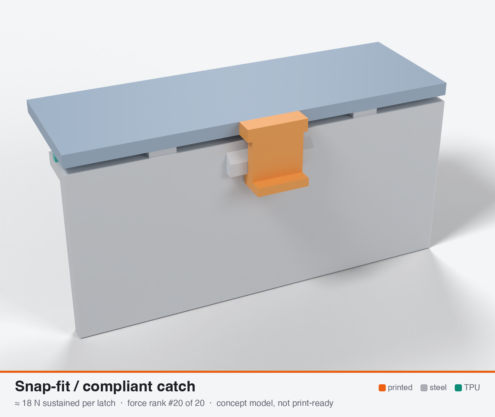
Per latch: 1 part to print, 2 items to buy, 3 features printed into the box or lid and the TPU 85A seal. Parts marked † are not drawn in the 3D model. In the 3D gallery you can click a part to see where it sits. The last column links the print file, or an example of the part in a shop (see the shopping list).
| Part | Qty | Type | What to use | File or shop |
|---|---|---|---|---|
| Snap arm | 1 | ASA, on its side so it flexes along the layers; 20 mm wide, 2.6 mm thick, about 24 mm long | snap-arm.stl | |
| Arm screws † | 2 | Buy | M3 × 8 A2/A4 socket screws (DIN 912) | Grobotronics |
| Square nuts † | 2 | Buy | M3 square nuts (DIN 562), pushed into the boss on the lid | Grobotronics |
| Screw boss | 1 | Printed with the lid | 20 × 10 × 6 mm block on the lid with two nut slots; the holes stop short of the lid | lid-coupon.stl |
| Catch ledge | 1 | Printed with the box | On the box wall, with a lead-in ramp | box-coupon.stl |
| Hard stops | 2 | Printed with the box | Pads on the rim either side of the latch, 1.6 mm tall: 0.8 mm below the free seal | box-coupon.stl |
| Seal strip | 1 | Seal (TPU 85A) | TPU 85A, 1.5 × 3.4 mm, in a 1.8 × 1.0 mm groove in the rim; the latch squeezes it 0.8 mm | seal-strip.stl |
Print files
Download all print files for this latch (ZIP, 40 kB)
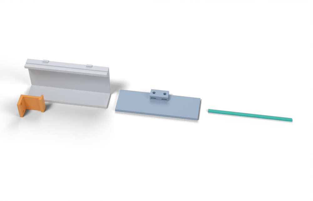
Print in ASA (TPU 85A for the seal), 0.2 mm layers, at least 4 walls; settings and the clearances used are in print/README.md. The parts are already turned the right way up for printing. The box and lid coupons are short test sections with this latch's box-side and lid-side features, so you can try the latch before building it into your own enclosure.
| File | Material | Qty | Size (mm) | How to print |
|---|---|---|---|---|
| snap-arm.stl | ASA | 1 | 23.6 × 17.8 × 20 | On its side, no supports, so the arm flexes along the layers. 2 × M3 × 8 into square nuts in the boss on the lid. |
| box-coupon.stl | ASA | 1 | 90 × 26 × 41.6 | Upright, no supports. A section of box wall with this latch's box-side features: seal groove, hard stops. Copy these features into your own box. |
| lid-coupon.stl | ASA | 1 | 90 × 30 × 9 | Flat, top up. A section of lid with this latch's lid-side features. Copy them into your own lid. |
| seal-strip.stl | TPU 85A | 1 | 90 × 3.4 × 1.5 | TPU 85A, 100 % infill, lying on its side. Press it into the rim groove: it stands 2.4 mm proud and the latch squeezes it 0.8 mm, until the lid lands on the hard stops. |
All printed parts in their assembled positions, for CAD: snap-fit-compliant.step.
How it works
A flexible arm (cantilever hook, annular snap, spring-loaded press-and-pull hook, bistable snap-through, or TPU/TPE strap) is deflected sideways while the lid closes. The hook slips past a ledge and the arm springs back so the hook sits behind the ledge. Holding is by geometric interference: the load goes through the arm as tension, and the arm relaxes to nearly zero strain once engaged. A rigid locking hook therefore adds no gasket preload. It only fixes the lid position, so the gasket force is whatever the tolerance stack gives. The one variant that stores preload is the stretched TPU/TPE strap or over-centre flexible draw latch, whose elastic stretch is the preload.
Mechanical advantage
About 1:1 for a locking hook, so the force at the lid equals the tension in the arm. Ramp geometry only governs insertion and removal: F_in = P(mu + tan a)/(1 - mu tan a). A pull-in wedge on the hook back face (10-20 deg) multiplies the arm's small spring force by only 1.1-1.6 at mu = 0.4. A TPU strap is also about 1:1 on strap tension, and an over-centre TPE latch such as the Gripwell C7 adds a small lever ratio.
What limits the force
Two limits. (1) Strength: the thin arm and hook root carry tension plus eccentric bending at 60-70 C. Sustained nominal stress is only ~3-5 MPa, so one catch holds ~10-25 N for a rigid hook and ~20-45 N for a 12x3 mm TPU strap. (2) No usable preload: a stiff hook cannot store or maintain gasket squeeze, and the arm cannot be pre-stressed (creep-limited deflection gives ~2 N). Even at the 28 mm rim-bending pitch, 20 N is only ~0.7 N/mm of line load, about a third of the 2 N/mm floor of the design window.
Analyst's calculation
Analyst's sustained estimate: 9–45 N, typical 20 N; peak 100 N.
Rigid locking hook, ASA or PETG, arm printed flat. Assumed arm L = 25 mm, t = 2.5 mm, b = 10 mm, E = 1.8 GPa (the lead's assumed value), I = b t^3/12 = 13.0 mm^4. Snapping: root strain = 1.5 t y / L^2. At the 3 % flat-arm limit (buildcad.ai rule: 3 % flat, 1.5 % standing for PETG/ABS/ASA) y_max = 5.0 mm and tip force P = 3EIy/L^3 = 22.5 N. A typical 1.5 mm hook gives 0.9 % strain and P = 6.8 N. With a 30 deg lead-in and mu = 0.4 the insertion force is 8.6 N, inside the measured ABS insertion range of 3.2-32 N (IJAME). Retention: tension through the arm with the hook face offset e = t/2 + h_hook/2 = 2 mm. Stress is sigma = (F/A)(1 + 6e/t) = 5.8 F/A, with Kt ~ 1.5 at the root fillet. At sustained sigma = 3 / 4 MPa (cautious) on the 2.5x10 arm: F = 8.6 / 11.5 N. A stouter arm (3.5x12 mm) at 4 / 5 MPa gives 21 / 26 N. At short-term XY tensile strength ~35 MPa (Bambu/Polymaker ASA 37 / 43.8 MPa XY, from the lead) the same arms break at ~100 N (2.5x10) to ~185 N (3.5x12). That is above the measured 41 N peak of the ABS release-type hooks, because those hooks were ramped to release. Use ~100 N as the realistic peak. Preload from the arm's own spring: creep-limited deflection at 0.3 % strain is 0.5 mm, giving P = 2.3 N, so the arm cannot be the preload spring. TPU strap: 12x3 mm = 36 mm^2, E ~ 12 MPa (NinjaFlex 85A, lead's link), 10-20 % stretch gives 43-86 N initially. After 30-50 % relaxation at 60-70 C (Ultrafuse 85A set 26-52 % is a compression-set proxy) the sustained force is ~22-60 N. Hence low 9 / typical 20 / high 45 N. Line load at 28 mm pitch: 9 / 20 / 45 N is 0.3 / 0.7 / 1.6 N/mm versus the 2-4 N/mm window. Series stiffness (own calc): rigid arm EA/L = 1800 N/mm against ~175 N/mm gasket stiffness per catch (rib 1.2x2.4 mm, 3 N/mm at 0.48 mm, 28 mm pitch). Loss = set x ks/(kg+ks) = 0.91 x set, so a 30-58 % compression set removes 27-53 % of the force. A TPU strap (~11 N/mm) loses <1 % to gasket set but relaxes itself. Commercial anchors: Gripwell C7 over-centre flexible latch (TPE latch, glass-filled nylon link, stainless keeper) lists clamping force 49 N (small) and 176 N (large). Evidence note: the WebSearch budget was exhausted in this run. Only URLs supplied by the lead were re-fetched; MakerWorld, Printables and Pelican returned 403 and are marked unverified.
Adversarial review
Independent recalculation (Python, same inputs): cantilever P = 3EIy/L^3 = 22.5 N, strain = 1.5 t y/L^2 = 3.0 % at y = 5 mm. Eccentric hook factor 1 + 6e/t = 5.8 (e = 2 mm, t = 2.5 mm). Sustained F = sigma A / (5.8 x 1.5) = 8.6 / 11.5 / 14.4 N at 3 / 4 / 5 MPa. Without Kt: 12.9 / 17.2 / 21.6 N. Stouter 3.5x12 arm, e = 2.5 mm: 21 N (Kt) to 32 N (no Kt) at 4 MPa. TPU strap 12x3 mm at 10-20 % stretch gives 43-86 N, then 30-50 % relaxation gives 22-60 N. Gasket stiffness per catch is 175 N/mm, arm stiffness is 1800 N/mm, so ks/(kg+ks) = 0.91. This matches the analyst (27-53 % loss). My typical of 18 N lies within about 10 % of the analyst's 20 N, and the key sources check out, so the verdict is confirmed. Scores are pulled back for seal and usability. A hook adds essentially no preload, so it is only a position-keeper beside a real clamp. Verified by fetch: buildcad.ai strain limits (PETG/ABS/ASA 3 % flat, 1.5 % standing, strain = 1.5 t y/L^2, fillet >= 0.5 t, arm >= 5 mm wide); IJAME (16 printed ABS models, insertion 3.23-32.18 N, retention 1.66-41.14 N, arm dimensions not on the page); CNC Kitchen hook test (ASA 57 vs 17 kg, PETG 55 vs 25, PLA 73 vs 40; ASA softens 110 C and fails 120 C; PETG fails about 85 C); filamentspecs (PETG joint lost about 11.5 % preload vs about 3 % PLA over 7 days, no conditions given); Gripwell C7 (49 N small, 176 N large, TPE latch, glass-filled nylon link, stainless keeper). MakerWorld 2385298 returns HTTP 403 for me too, so it stays unverified.
Issues raised:
- Arithmetic reproduces: I = 13.0 mm^4, tip force 22.5 N at 3 % strain (y = 5 mm), 6.75 N at 0.9 % strain. Retention at the hook root is 8.6 / 11.5 N (3 / 4 MPa) for 2.5x10 mm and about 21 / 26 N for 3.5x12 mm. The analyst applies the 3-5 MPa allowable to the peak local stress (eccentric bending x Kt 1.5). That is conservative, because creep relieves Kt under static load. Without Kt the same arms hold 13-22 N and 21-40 N. The spread 9-45 N is therefore defensible, with the typical value slightly under 20 N.
- A rigid hook is not a clamp. At the design rib (3 N/mm at 0.48 mm, 28 mm pitch) the gasket pushes back about 84 N per hook, 4-8x what the hook can hold sustained. Holding 11-25 N means a squeeze of only 0.06-0.14 mm, below FDM warp and below the 0.2 mm minimum squeeze in the brief. A snap-fit cannot seal the design gasket, so seal_suitability 3 is pulled to 2.
- Usability 8 only holds for a very soft or sparse gasket. The user must compress the gasket by hand while the hook engages, and the design-window reaction is 1.4-2.8 kN on a 200x150 lid. Scored 6.
- The TPU strap loss to gasket set is stated as under 1 %. Recomputed: strap 36 mm^2 x 12 MPa / 40 mm = 10.8 N/mm against 175 N/mm of gasket, so ks/(kg+ks) = 0.058 and the set loss is 1.8-3.4 %. The strap's own stress relaxation at 60-70 C (30-50 %) still dominates.
- Peak of 100 N is an upper estimate. It comes from the in-plane XY strength (about 35 MPa) divided by eccentricity and Kt, which gives 86-115 N. The only measured retention data (IJAME, release-type ABS hooks) top out at 41 N, and the larger CNC Kitchen hook (57 kg lying) is a much stouter geometry. Used 90 N. This is a room-temperature break load, not a hot value.
- Evidence is thin. There is no sustained-load creep data for ASA or PETG at 60-70 C anywhere in the cited set. Dogan 2022 only shows ABS rupturing in about 3 min at 60 C and 20 MPa (milled specimens, 3 h tests). The 3-5 MPa rule is untested judgement.
- The Gripwell 49 / 176 N figures are catalogue 'clamping force' ratings. The PDF does not say whether they are working, sustained or break loads. The Southco and temperature claims are not in the PDF, as the analyst already noted. Treat the PDF as an order-of-magnitude anchor for a TPE draw latch only.
Preload retention outdoors
Poor for rigid hooks. They are stiff (ks/(kg+ks) ~ 0.9), so 27-53 % of the force is lost to TPU compression set at 70 C. FDM hook-to-ledge slack of a few tenths of a mm is as large as the whole 0.2-0.75 mm gasket stroke, so the lid can lift and the force falls to ~0. Arm tension creep at 60 C adds loss. The TPU strap variant is much softer, so gasket set costs <1 %, but the strap relaxes 30-50 % itself and loses strength in UV (TPU 92A -15 % after 1000 h QUV, lead's Stratasys source).
Materials
ASA is the default (arm printed flat, 4+ perimeters, 0.2 mm or finer layers). UV-stabilised PC is tougher and creeps less, probably 1.3-1.5x higher limits (the lead's own judgement, unmeasured). PETG is marginal at 60-70 C (HDT 68 C). Avoid PLA and unstabilised PP. PA6-CF is out outdoors (3.3 % water uptake). For the strap variant use black UV-stabilised TPU or TPE/EPDM straps.
Hardware notes from the research
None for the printed hook. Optional A2/A4 stainless compression spring for press-and-pull variants. A stainless keeper with a radiused edge for TPU straps. A 3 mm stainless pin if the catch is hinged.
Design guidelines
- Print arms lying flat so bending stress runs along the roads, and keep all hook and ledge loads in XY. A standing arm bears ~29 % (ASA, 17 vs 57 kg hook test) to 46 % (PETG) of the lying strength (CNC Kitchen).
- Snapping strain at the root <= 3 % flat or 1.5 % standing (strain = 1.5 t y / L^2). Lengthen the arm before thinning it. Typical arm L 25-30 mm, t 2.5-3.5 mm, b >= 10 mm (buildcad.ai says >= 5 mm).
- Root fillet >= 0.5 t and never under 0.4 mm. Aim for 1.5 mm in ASA, which has only ~3 kJ/m2 notched Charpy at -30 C.
- 30 deg lead-in. Square or 3-5 deg undercut back face for a positive lock. Do not count on a pull-in wedge for preload (gain only 1.1-1.6).
- The engaged arm must be at ~0 strain, because sustained strain above ~0.3 % creeps at 60-70 C. Treat the snap as alignment and retention only.
- Space catches at or below the rim-bending pitch (~28 mm for a flat 3 mm lid edge, ~110 mm with a 20 mm skirt). Put a printed hard stop beside each catch at 0.75-0.8x the free bead height.
- Use snaps beside a screw, cam or band clamp that supplies the preload. If the gasket line load is above ~1 N/mm, a snap-only closure cannot hold it.
- TPU strap: 12-15 x 3 mm, 15-20 % stretch, 2-3 keeper positions for adjustment, UV-stabilised black, replaceable. Expect to retension it after the first hot summer.
Failure modes
- Root crack from cold or fatigue (sharp internal corners, standing arm)
- Hook lift-off from creep of the arm or ledge at 60-70 C, so the gasket force is lost
- Hook rotating out of the ledge under the eccentric closing load
- Gasket compression set shows up almost 1:1 as force loss (stiff hook)
- Rim bowing between catches leaves leak gaps
- TPU strap relaxation and UV embrittlement
- Vibration or thermal cycling unseating a bistable or press-and-pull catch
- Inconsistent squeeze from FDM tolerance, with no adjustment
Existing designs and commercial references
- MakerWorld Rugged Waterproof Tough Case 2385298 (PETG snap latches + TPU 85A gasket) — Only printed-latch-plus-85A-TPU design known to the lead. No force or IP data. Re-fetch returned HTTP 403, so unverified.
- zx82net ultimate parametric rugged box snap closure (Printables) — From the lead. Re-fetch returned HTTP 403, so unverified.
- Thingiverse clip-latch rugged box with filament pins (harktech mirror) — PLA+ 15 % infill, no test (from the lead; not re-fetched).
- [Gripwell C7 flexible over-centre draw latch (commercial TPE reference, not printable)](https://www.gripwell.com.sg/image/catalog/Gripwell/Engineered Access Hardware/Latches/Draw Latches/C7 Flexible Draw Latch/Gripwell - C7 Flexible Draw Latch.pdf) — Verified: clamping force 49 N small / 176 N large; TPE latch, glass-filled nylon link, stainless keeper. The lead's 'Southco EPDM' and -20 to 95 C figures were not found in this PDF.
- Pelican Storm iM2435 spec sheet (PBT latch + EPDM O-ring) — Press-and-pull reference, no force published. Re-fetch returned 403.
Evidence gathered in the sweep
SUSTAINED (own est.): snap-fit 10-30 N per catch, TPU strap latch ~20-100 N once relaxed; PEAK 40-120 N snap, TPU strap 49-176 N new. MEASURED: ABS cantilever hooks (16 geometries) retention 1.7 to ~41 N, insertion ~3-34 N https://journal.ump.edu.my/ijame/article/view/11091 ; strain rules https://buildcad.ai/snap-fit-3d-printing ; Southco EPDM flexible latch 49 N, -20 to 95 C and Gripwell C7 49-176 N https://www.gripwell.com.sg/image/catalog/Gripwell/Engineered Access Hardware/Latches/Draw Latches/C7 Flexible Draw Latch/Gripwell - C7 Flexible Draw Latch.pdf ; Pelican Storm iM2435: PBT latch plus EPDM O-ring, no force published https://www.pelican.com/us/en/product/cases/iM2435/pdf ; MakerWorld Tough Case 2385298 pairs PETG snap latches with a TPU 85A gasket, no force or IP data https://www.makerworld.com/en/models/2385298 ; zx82net snap closure https://www.printables.com/model/59227-zx82net-ultimate-parametric-rugged-box-snap-closur ; Thingiverse clip-latch rugged box with filament pins, PLA+ 15 % infill, no test https://harktech.co.uk/m/thingiverse/7208214 . Not suitable for solid 85A TPU. CONFIDENCE: medium for the ranking, low for numbers.
Sources
- Analyzing insertion and retention forces in cantilever snap-fits (IJAME) — Verified: 16 printed ABS geometries, experimental insertion 3.2-32.2 N, retention 1.66-41.1 N; Model 5 highest retention, Model 2 lowest.
- buildcad.ai snap-fit 3D printing rules — Verified: allowable strain PETG/ABS/ASA 3 % flat and 1.5 % standing, PLA 2 %/1 %; strain = 1.5 t y/L^2; fillet >= 0.5 t; arm width >= 5 mm; 30 deg lead-in. No retention formula or creep data.
- CNC Kitchen: Comparing PLA, PETG and ASA (Prusament) — Verified: hook failure lying vs standing ASA 57 vs 17 kg, PETG 55 vs 25, PLA 73 vs 40; ASA softens 110 C, fails 120 C; PETG fails ~85 C.
- [Gripwell C7 flexible draw latch datasheet](https://www.gripwell.com.sg/image/catalog/Gripwell/Engineered Access Hardware/Latches/Draw Latches/C7 Flexible Draw Latch/Gripwell - C7 Flexible Draw Latch.pdf) — Verified by decoding the PDF: clamping force 49/176 N, over-centre, TPE.
- filamentspecs: creep resistance of 3D printed parts — Verified: bolted PETG joints lost ~11.5 % preload in 7 days vs ~3 % PLA. The page gives no numeric stress or temperature limits for ASA, PETG, nylon or PC.
- Texin 985 datasheet (gasket stress and compression set) — From the lead's brief; not re-fetched. Gasket stiffness figures here are own calc from it.
- Stratasys FDM UV ageing white paper — From the lead (TPU 92A -15 % after 1000 h QUV, ASA -3 % break stress); not re-fetched.
Sources the reviewer flagged (dead, blocked or misdescribed):
- https://www.makerworld.com/en/models/2385298 returned HTTP 403 on re-fetch, so the 'only printed latch plus TPU 85A gasket design' claim cannot be checked
- https://www.printables.com/model/59227-zx82net-ultimate-parametric-rugged-box-snap-closur and https://www.pelican.com/us/en/product/cases/iM2435/pdf were reported 403 by the analyst; I did not re-check them
- https://journal.ump.edu.my/ijame/article/view/11091 is quoted correctly but gives no arm dimensions and does not define 'retention force'. It cannot support a locking-hook sustained load
- https://filamentspecs.com/creep-resistance-3d-printed-parts/ is quoted correctly (11.5 % vs 3 %) but the page gives no bolt, preload, stress or temperature, and itself warns against transferring the percentages
- https://sushengpolymer.com/media/pdf/phFiH7_Texin-985.pdf: the compression table is an embedded raster image, so my fetch could not read it. The gasket stiffness inputs are not independently verified by me