No. 19 of 20 · Rectangular lids
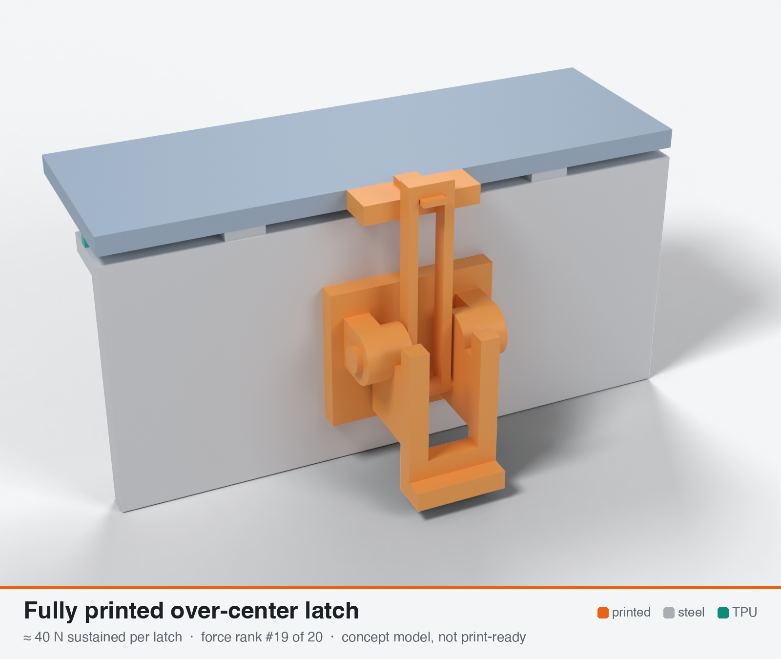
Fully printed over-center latch
Fully printed over-center draw latch (assembled hooks-over-pivots or print-in-place)
- Force rank
- 19 of 20
- Latches for the reference lid
- 35–70
- Build
- Fully printed
- Hand force to close
- ≈ 6 N
- Adjustable preload
- no
- Positive compression stop
- no
- Force basis
- estimated
- Review verdict
- corrected
- Confidence
- low
Verdict: Printed posts loaded across layers and C-hook creep limit it (post bending 25-34 N for a 9 mm post standing). Print-in-place posts reach only about 10 N. About 0.46 N/mm with 8 latches. No steel to fix it.
On this page
Parts
Per latch: 5 parts to print, 2 items to buy, 3 features printed into the box or lid and the TPU 85A seal. Parts marked † are not drawn in the 3D model. In the 3D gallery you can click a part to see where it sits. The last column links the print file, or an example of the part in a shop (see the shopping list).
| Part | Qty | Type | What to use | File or shop |
|---|---|---|---|---|
| Base | 1 | ASA, flat on its back; ears with 4.25 mm bores | base.stl | |
| Lever | 1 | ASA, on its side with supports under the upper cheek | lever.stl | |
| Pivot pins | 2 | ASA, lying on the flat; glued into the lever cheeks | pivot-pin.stl | |
| Axle pin † | 1 | ASA, lying on the flat; pressed through the cheeks and the loop | axle-pin.stl | |
| Loop link | 1 | ASA, on its side; bars 2.2 × 3.3 mm | loop-link.stl | |
| Base screws † | 2 | Buy | M3 × 10 A2/A4 socket screws (DIN 912) | Grobotronics |
| Square nuts † | 2 | Buy | M3 square nuts (DIN 562), dropped down the channels in the box wall | Grobotronics |
| Keeper with horn | 1 | Printed with the lid | Ledge on the lid edge with a 2.2 mm horn the loop hooks over | lid-coupon.stl |
| Hard stops | 2 | Printed with the box | Pads on the rim either side of the latch, 1.6 mm tall: 0.8 mm below the free seal | box-coupon.stl |
| Nut channels | 2 | Printed with the box | Inside pillar with a 5.7 × 2.0 mm channel per nut, open on the rim outside the seal; blind 3.4 mm screw holes, so no path into the box | box-coupon.stl |
| Seal strip | 1 | Seal (TPU 85A) | TPU 85A, 1.5 × 3.4 mm, in a 1.8 × 1.0 mm groove in the rim; the latch squeezes it 0.8 mm | seal-strip.stl |
Print files
Download all print files for this latch (ZIP, 0.1 MB)
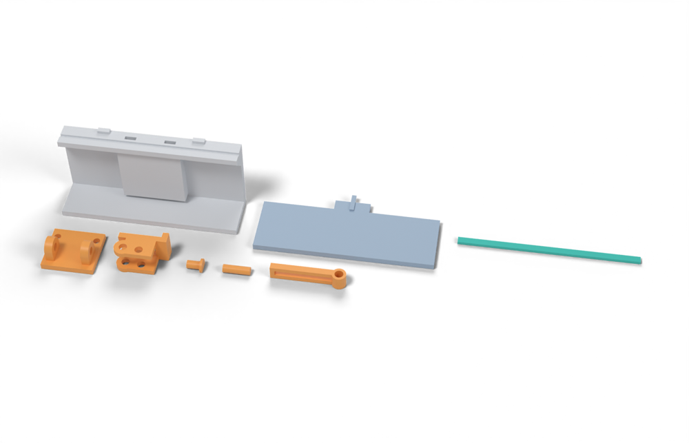
Print version: The loop runs on a separate printed axle pin rather than a bar moulded into it, so it can be assembled; the pivot pins are printed with heads.
Print in ASA (TPU 85A for the seal), 0.2 mm layers, at least 4 walls; settings and the clearances used are in print/README.md. The parts are already turned the right way up for printing. The box and lid coupons are short test sections with this latch's box-side and lid-side features, so you can try the latch before building it into your own enclosure.
| File | Material | Qty | Size (mm) | How to print |
|---|---|---|---|---|
| base.stl | ASA | 1 | 26 × 24 × 13 | Flat on its back, no supports. 2 × M3 × 10 into the box. The pivot pins turn in these bores. |
| lever.stl | ASA | 1 | 24.5 × 16.5 × 13.5 | On its side (pin axis vertical), supports under the upper cheek. Press the pivot pins and the link pin into the 3.9 mm holes. |
| pivot-pin.stl | ASA | 2 | 7.9 × 7 × 5.2 | Lying on its flat. Press into the lever cheek from outside the base ear; a drop of glue holds it. |
| axle-pin.stl | ASA | 1 | 13.5 × 4 × 3.7 | Lying on its flat. Pressed through the lever cheeks and the loop's eye. |
| loop-link.stl | ASA | 1 | 37.2 × 7 × 7.2 | On its side, no supports, so the bars pull along the layers; the upper bar bridges. |
| box-coupon.stl | ASA | 1 | 90 × 24 × 41.6 | Upright, no supports. A section of box wall with this latch's box-side features: seal groove, hard stops, and an inside pillar with nut channels. Push an M3 square nut down each of the 2 channels in the rim before fitting the screws. Copy these features into your own box. |
| lid-coupon.stl | ASA | 1 | 90 × 40 × 3.9 | Flat, top up. A section of lid with this latch's lid-side features. Copy them into your own lid. |
| seal-strip.stl | TPU 85A | 1 | 90 × 3.4 × 1.5 | TPU 85A, 100 % infill, lying on its side. Press it into the rim groove: it stands 2.4 mm proud and the latch squeezes it 0.8 mm, until the lid lands on the hard stops. |
All printed parts in their assembled positions, for CAD: oc-fully-printed.step.
How it works
Lever, link and hook are all printed; the pivots are printed posts that C-shaped hooks snap over (assembled), or clearance-gapped joints printed in place. The lever passes dead centre and locks without friction, but clamping force depends on the elastic stretch of the printed hook and pivot posts. Light preload only: the 85A bead needs a stiffer path, and printed pivots creep and wear.
Mechanical advantage
Lever 50 mm, e = 8 mm, engagement stroke 1.0 mm (my calc): geometric MA at the worst point = 50/1.54 = 32:1; about 11:1 after friction (mu 0.35 printed-on-printed, 9 mm posts). Static MA at lock (0.5 mm offset) about 100:1. The load is limited by the printed posts, not by the MA.
What limits the force
Bending of the printed pivot posts (in-plane 3-5.5 MPa, across layers only 2 MPa) and creep stretching of the C-hooks. The print-in-place version is further limited by small posts and 0.3-0.4 mm gaps.
Analyst's calculation
Analyst's sustained estimate: 25–95 N, typical 60 N; peak 250 N.
ASSEMBLED VERSION (my choice): integral posts d = 9 mm lying with the axis in the layer plane, supported by two ears 6 mm each with a 17 mm span, lever 12 mm, C-hook back wall 3 mm, ASA, 5 perimeters. Post bending: Z = pi d^3/32 = 71.6 mm3; M = F L/4 = 4.25 F mm; sigma = 0.0594 F. At 3 / 4 / 5.5 MPa (in-plane) the post allows 51 / 67 / 93 N. If the post stands (axis Z, bending across layers, 2 MPa): 34 N. PRINT-IN-PLACE posts d = 5 mm, span 10 mm: Z = 12.3 mm3, sigma = 0.203 F -> 15-27 N in-plane, 10 N standing (gaps and fused layers are not accounted for). Sustained estimate for the family: low 25 (PIP or standing post), typical 60, high 95 N. PEAK: C-hook opening and ear root, not post bending (post alone would carry far more): about 250 N (100-400). The MakerWorld Draw Latch survived about 187 N and stretched out of position, so it is a lower bound for PLA-class parts, and ASA sustained of about 0.27 x 187 = 50 N (ratio from the 4 MPa / 15 MPa nominal stresses above) matches the 60 N typical. HAND FORCE: (1.54 F geometric + 3.15 F friction) = 4.7 F mm; at 60 N and 50 mm that is about 6 N. FIT TO LOAD: 8 latches x 60 N = 480 N = 0.7 N/mm on a 700 mm path, a third of the 2 N/mm window. It only works at 30 mm pitch (60 N / 30 mm = 2 N/mm), roughly the rim-bending pitch of a flat 3 mm lid edge (28 mm), i.e. 20+ latches, or with a much narrower, softer rib. EVIDENCE STATUS: no sustained printed test found; the web-search budget was exhausted in this run, so the printed-latch values rest on the brief's anecdotes (Draw Latch, 187 N). Confidence low.
Adversarial review
Recomputed: post section modulus 71.6 mm3, bending coefficient 0.0594 sigma/N, allowable 34/51/67/93 N at 2/3/4/5.5 MPa (matches). Print-in-place post (5 mm, 10 mm span) 10/15/20/27 N. Friction hand force 4.7 F mm / 50 mm lever gives about 5 N at 40 N, fine. Preload retention: kl 300 N/mm gives set loss 13.8 % at 52 % set, and cold +17 % (match), but creep of the C-hook is unquantified and likely dominates. The orientation conflict is the substantive correction, because the stated high-end values need in-plane loading of a post whose lever and hook cannot also be loaded in-plane. Hardware-free printing is the real advantage, but it cannot supply gasket force. Scores: seal stays at 2, durability 5 to 4, printability 9 to 8, usability 6 unchanged.
Issues raised:
- The typical of 60 N relies on printed posts lying with their axis in the layer plane. That makes the lever, link and C-hook planes contain Z, so their loads, including lever bending along the arm, run across layers. This contradicts the analyst's own rule of pin axes along Z and loads in-plane. The self-consistent orientation (axis along Z) gives the analyst's own post figure of 34 N for a 9 mm post at 2 MPa (about 25 N with a root fillet), and about 10 N for a 5 mm print-in-place post. A realistic family typical is about 40 N.
- The 187 N Draw Latch result is the only anchor and could not be fetched. The material is unknown, and the model 'stretched out of position', so it was creeping or yielding at 187 N. The 0.27 ratio is derived from the same allowables, so the claim that it 'matches' 60 N is circular.
- At 40 N sustained, 8 latches give 320 N on 700 mm, which is 0.46 N/mm, about 4-8x below the 2-4 N/mm window. The pitch needed to reach 2 N/mm is 20 mm, which is not practical. It is unsuitable for 85A TPU ribs and only works with a very thin, soft bead.
- Printed-on-printed pivots at 60-70 C with mu 0.35 wear and ovalise, and an ASA print-in-place joint with a 0.3-0.4 mm gap tends to fuse or warp. Durability 5 to 4, printability 9 to 8.
- Peak 250 N is not supported by anything fetched. Across-layer post bending at about 12-15 MPa peak gives 200-250 N, and in-plane about 500 N. C-hook lips yield first. I report 200 N (100-350).
Preload retention outdoors
Poor and uncertain. Printed latch structure k_l about 300 N/mm (assumed; the compliance is what lets the lever close): set loss = 0.52 x 300/(300 + 830) = 14 % at 70 C, 7 % at 23 C. The dominant loss is plastic creep of the C-hooks and posts, which is unquantified; the MakerWorld Draw Latch stretched out of position at about 187 N, and PETG bolted joints lost 11.5 % preload in a week. My estimate is 20-50 % loss in the first hot season. Cold: +17 % at -30 C (220 -> 258 N/mm). Not adjustable.
Materials
ASA first; UV-stabilised PC for the best creep and heat margin (my judgement, probably 1.3-1.5x). PETG is too soft hot (HDT 68 C) and creeps. PA6-CF is out for moisture; PAHT-CF acceptable but still creeps. Avoid unstabilised PP outdoors (months). 3 mm A4 steel pins to harden the pivots turn this into the fixed-hook latch.
Hardware notes from the research
None required. Optional 3 mm A4 pins to harden pivots (that makes it the pinned fixed-hook latch).
Design guidelines
- Walls of at least 1.2 mm per wall class, 5 perimeters, ASA or PC, 0.15-0.2 mm layers, link and hook printed on their sides (in-plane loads).
- Posts at least 9 mm for assembled latches, lying with the axis in the layer plane; never standing.
- Print-in-place gap 0.3-0.4 mm for a 0.4 mm nozzle, widened to 0.5 mm outdoors for grit; expect lower strength than assembled.
- Internal fillets R 2 mm or more; thick C-hook back walls (3 mm or more); ears at least 6 mm.
- Keep the load in the back of the C-hook, not on the opening lips.
- Use only with a thin, soft rib or at 30 mm pitch or less; add a printed hard stop at 0.75-0.8x the free bead height.
- Upgrade path: drill for 3 mm A4 pins and turn the latch into the fixed-hook pinned version.
Failure modes
- C-hook lips open or stretch (the lever creeps out of dead centre) under months of load or a hot afternoon.
- Post shear or bending crack at the root, especially if printed standing or in cold ASA.
- Print-in-place joints fuse or bind, or grit and ice jam the gaps.
- Printed pivots wear and gain play, so the over-center offset is lost.
- UV embrittlement of thin sections in unstabilised materials (PC, PETG).
- Too little force for the gasket: weeps at 85A rib squeeze.
Existing designs and commercial references
- MakerWorld Draw Latch 2266330 — survived about 42 lb (187 N) but stretched out of position (carried from the brief, HTTP 403)
- Sturdy print-in-place draw latch (Printables) — designer says it is weaker than metal latches (carried from the brief, HTTP 403)
- Wider sturdy latch with optional reinforced mount (Printables) — wider print-in-place variant (carried from the brief)
- MakerWorld Waterproof Latch Sealed Boxes, Print-in-Place 2435156 — 5 mm walls; splash-proof without gasket, almost waterproof with TPU 95A, no test data (carried from the brief)
- Replacement for Pentair LXLATCH (STLFinder) — original moulded latches broke after about 10 years in sun; reprint in ABS/PETG/PC (carried from the brief)
- MakerWorld Tough Case 2385298 — only printed-latch-plus-85A-TPU design found: PETG snap latches, no force or IP data (carried from the brief)
Evidence gathered in the sweep
SUSTAINED (own est., ASA): assembled 40-100 N, print-in-place 25-60 N, sturdy PIP 15-40 N; PEAK 100-400 N. EVIDENCE: Draw Latch 2266330 survived ~187 N (lower bound) https://makerworld.com/en/models/2266330-draw-latch ; print-in-place latch box 2435156, 5 mm walls, splash-proof without gasket, 'almost waterproof' with TPU 95A, no test data https://makerworld.com/models/2435156 ; Sturdy PIP draw latch, designer says weaker than metal latches https://www.printables.com/model/130254-sturdy-print-in-place-draw-latch ; wider reinforced-mount version https://www.printables.com/model/1388482-wider-sturdy-latch-with-optional-reinforced-mount ; Pentair replacement: original moulded latches broke after ~10 years in sun, reprint in ABS/PETG/PC https://www.stlfinder.com/model/replacement-for-pentair-lxlatch-NuK4TAoL/5223236 . CONFIDENCE: low.
Sources
- MakerWorld Draw Latch 2266330 — 187 N lower bound; carried from the brief
- Sturdy print-in-place draw latch (Printables) — carried from the brief; fetch returned 403
- Replacement for Pentair LXLATCH (STLFinder) — field evidence: moulded latches lasted about 10 years in sun; carried from the brief
- CNC Kitchen: comparing PLA, PETG and ASA (hook tests) — fetched: ASA lying 57 kg vs standing 17 kg
- Creep resistance of 3D printed parts (filamentspecs) — fetched: bolted PETG lost 11.5 % preload in 7 days vs 3 % for PLA; no ASA data
- Ultrafuse TPU 85A TDS — 52 % set at 70 C; value taken from the brief
Sources the reviewer flagged (dead, blocked or misdescribed):
- https://makerworld.com/en/models/2266330-draw-latch (HTTP 403; the 187 N / 42 lb figure is unverified)
- https://www.printables.com/model/130254-sturdy-print-in-place-draw-latch (HTTP 403; unverified)
- https://www.printables.com/model/1388482-wider-sturdy-latch-with-optional-reinforced-mount (not fetched)
- https://makerworld.com/models/2435156 (not fetched)
- https://www.stlfinder.com/model/replacement-for-pentair-lxlatch-NuK4TAoL/5223236 (HTTP 403; the ten-year field note is unverified)
- https://www.makerworld.com/en/models/2385298 (HTTP 403; the PETG snap latch with 85A TPU gasket is unverified)
- https://filamentspecs.com/creep-resistance-3d-printed-parts/ (opens; the 11.5 % / 3 % figures are study-specific, with no ASA data and no temperature)
- https://www.dream3d.co.uk/wp-content/uploads/2022/12/Ultrafuse_TPU_85A_TDS_EN_v2.5.pdf (not machine-readable here; not re-checked)