No. 18 of 20 · Rectangular lids
Stainless wire bail latch
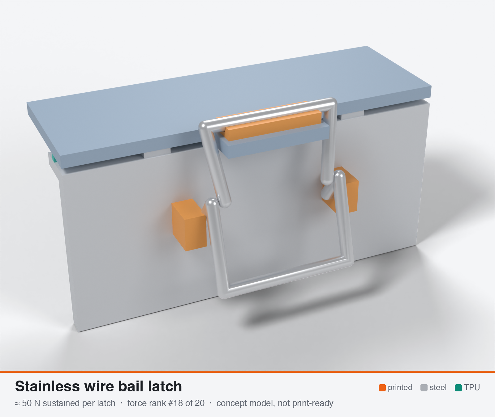
Stainless wire bail latch with printed retainers
- Force rank
- 18 of 20
- Latches for the reference lid
- 28–56
- Build
- Printed + steel hardware
- Hand force to close
- ≈ 20 N
- Adjustable preload
- no
- Positive compression stop
- no
- Force basis
- estimated
- Review verdict
- corrected
- Confidence
- medium
Verdict: The wire (steel) is not the limit. The printed catch hook is (about 7 MPa at 60 N). Good retention because the wire acts as the spring. 28-56 latches would be needed on the reference lid.
On this page
Parts
Per latch: 1 part to print, 4 items to buy, 3 features printed into the box or lid and the TPU 85A seal. Parts marked † are not drawn in the 3D model. In the 3D gallery you can click a part to see where it sits. The last column links the print file, or an example of the part in a shop (see the shopping list).
| Part | Qty | Type | What to use | File or shop |
|---|---|---|---|---|
| Wire retainers | 2 | ASA, on end; blind 3.3 mm hole for the wire (the left one is retainer-left.stl) | retainer-right.stl | |
| Lever wire | 1 | Buy | 3 mm stainless wire, about 110 mm, bent to shape | Gutekunst |
| Bail | 1 | Buy | 3 mm stainless wire, about 45 mm, bent to shape | Gutekunst |
| Retainer screws † | 4 | Buy | M3 × 16 A2/A4 socket screws (DIN 912) | Grobotronics |
| Square nuts † | 4 | Buy | M3 square nuts (DIN 562), dropped down the channels in the box wall | Grobotronics |
| Catch ridge | 1 | Printed with the lid | Ridge on the lid tab with a groove for the bail | lid-coupon.stl |
| Hard stops | 2 | Printed with the box | Pads on the rim either side of the latch, 1.6 mm tall: 0.8 mm below the free seal | box-coupon.stl |
| Nut channels | 4 | Printed with the box | Inside pillar with a 5.7 × 2.0 mm channel per nut, open on the rim outside the seal; blind 3.4 mm screw holes, so no path into the box | box-coupon.stl |
| Seal strip | 1 | Seal (TPU 85A) | TPU 85A, 1.5 × 3.4 mm, in a 1.8 × 1.0 mm groove in the rim; the latch squeezes it 0.8 mm | seal-strip.stl |
Print files
Download all print files for this latch (ZIP, 71 kB)
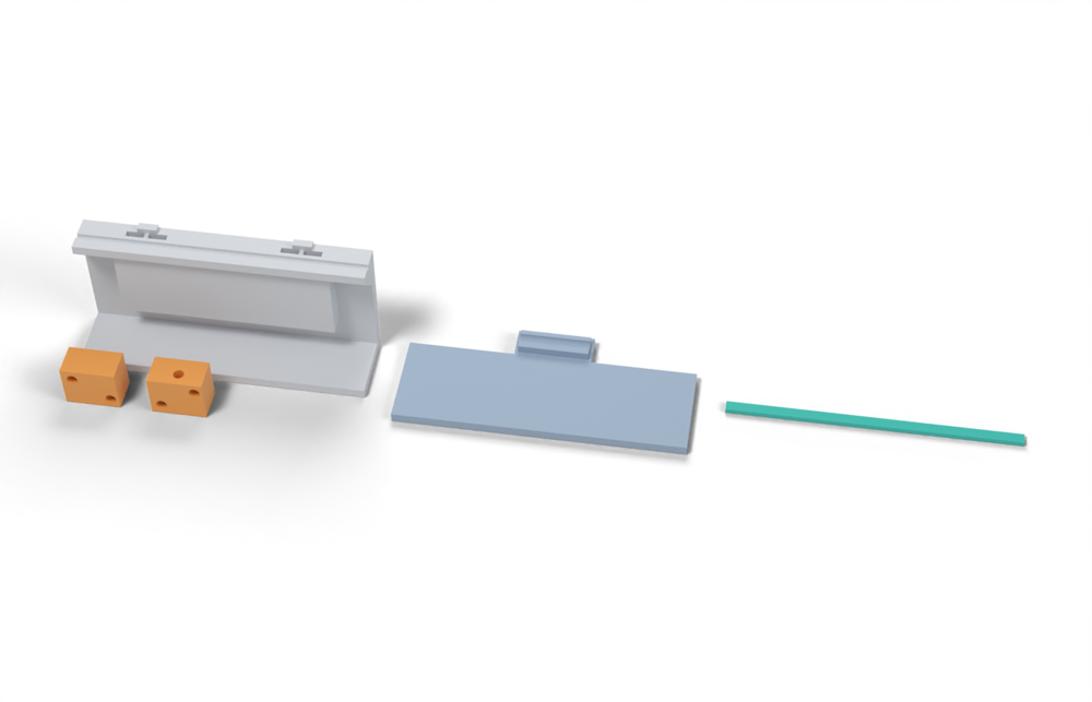
Print in ASA (TPU 85A for the seal), 0.2 mm layers, at least 4 walls; settings and the clearances used are in print/README.md. The parts are already turned the right way up for printing. The box and lid coupons are short test sections with this latch's box-side and lid-side features, so you can try the latch before building it into your own enclosure.
| File | Material | Qty | Size (mm) | How to print |
|---|---|---|---|---|
| retainer-right.stl | ASA | 1 | 17 × 10 × 13.8 | On its end (wire hole vertical), no supports. Blind 3.3 mm hole for the 3 mm lever wire. 2 × M3 × 16 into the box. |
| retainer-left.stl | ASA | 1 | 17 × 10 × 13.8 | On its end (wire hole vertical), no supports. Blind 3.3 mm hole for the 3 mm lever wire. 2 × M3 × 16 into the box. |
| box-coupon.stl | ASA | 1 | 90 × 24 × 41.6 | Upright, no supports. A section of box wall with this latch's box-side features: seal groove, hard stops, and an inside pillar with nut channels. Push an M3 square nut down each of the 4 channels in the rim before fitting the screws. Copy these features into your own box. |
| lid-coupon.stl | ASA | 1 | 90 × 40 × 5.6 | Flat, top up. A section of lid with this latch's lid-side features. Copy them into your own lid. |
| seal-strip.stl | TPU 85A | 1 | 90 × 3.4 × 1.5 | TPU 85A, 100 % infill, lying on its side. Press it into the rim groove: it stands 2.4 mm proud and the latch squeezes it 0.8 mm, until the lid lands on the hard stops. |
All printed parts in their assembled positions, for CAD: bail-wire-latch.step.
How it works
A bent 304/316 stainless wire bail pivots in two printed holders on the base. Its short arm forms an over-center cam that drops into a printed catch on the lid. The wire flexes elastically as the bail goes over center. That flex is the clamp force, so the energy is stored in steel and not in plastic. Force is set by wire deflection, so it is spring-controlled and self-limiting. It is not stroke-controlled. Printed parts only hold the wire ends and form the cam seat and catch, and they see a low stress of about 3 MPa.
Mechanical advantage
Handle-to-cam lever ratio about 3:1 (45 mm handle, 15 mm cam arm), plus over-center holding. The clamp force is NOT hand force x lever ratio. It is wire stiffness x deflection, about 53 N/mm per leg for 3 mm wire with a 35 mm free length. The lever ratio only sets how little hand force is needed.
What limits the force
Wire bending stiffness and allowable stress in a package that fits the 70x35x30 mm envelope. Bail legs of 3 mm wire and 25-35 mm length cap out at about 120-170 N. Beyond that the printed holder or catch breaks, or the wire takes a set. It is not a latch for a 1.4-2.8 kN lid unless there are 25-45 of them.
Analyst's calculation
Analyst's sustained estimate: 25–120 N, typical 60 N; peak 250 N.
NO MEASURED DATA: the web-search tool refused new searches (budget exhausted) and the printable-model pages returned HTTP 403, so this is a first-principles estimate. ASSUMPTIONS: 304 spring-temper wire, d = 2-3 mm. UTS at 2.5-3 mm is assumed ~1,500-1,700 MPa (own value). Lee Spring only quotes 275-300 ksi for fine wire: https://www.leespring.com/music-wire-versus-stainless-steel (fetched and confirmed; also confirms 302/304 usable to about 288-316 C and music wire to about 121 C and rusting). Bail leg is a cantilever of free length L = 35 mm (25 mm for a stiff variant), E = 190 GPa. The sustained bending allowable is taken as 600-1,100 MPa (about 0.4-0.7 of UTS, no set, no stress relaxation at 70 C). F_leg = sigma x (pi d^3/32)/L. RESULTS at 800 MPa: d=3.0, L=35 gives 61 N per leg, 121 N for two legs. d=2.5 gives 70 N for two legs. d=2.0 gives 36 N. d=3.0, L=25 gives 170 N (spring rate 290 N/mm). At 600-1,100 MPa, d=3/L=35 spans 91-167 N. SPRING RATE: k = 3EI/L^3 = 53 N/mm per leg (106 N/mm for two) for d=3, L=35, and deflection at the limit is 1.15 mm, comfortably larger than the 0.2-0.75 mm gasket stroke. GASKET STIFFNESS from Texin 985 (4.31-2.07 MPa between 10 and 20 % squeeze, 1.2 x 2.4 mm rib): 11.2 N/mm per mm of rib, which is 336 N/mm per latch at 30 mm pitch and 1,120 N/mm at 100 mm pitch. So the wire is 3-10x softer than the gasket. PRELOAD LOSS from set = 0.52 x ks/(kg+ks) = 11 % (30 mm pitch) to 4 % (100 mm pitch). PRINTED PART CHECK: wire in a 3 mm hole through a 6 mm wall carries 60 N at 3.3 MPa bearing, well below the 8-10 MPa working rule. PEAK: wire yield at about 1,100-1,300 MPa is roughly 230 N (3 mm wire), and printed holder/catch bearing at about 20 MPa short term over 18 mm2 is about 360 N. The hook root of the catch breaks first, so peak is taken as 250 N. WHAT IT MEANS FOR THE GASKET: line load = latch force / pitch. 60 N at 30 mm pitch is 2 N/mm and 120 N at 30 mm pitch is 4 N/mm. For the 700 mm reference path, 1.4-2.8 kN would need about 12-47 bail latches, which is not practical. Useful only for small boxes or light 1.2 mm ribs at 30-40 mm pitch. Hand force to close at 60 N is about 60/3 = 20 N plus the over-center snap.
Adversarial review
Independent recomputation. Wire: Z = pi d^3/32 = 2.651 mm3, I = 3.976 mm4, k = 3EI/L^3 = 52.9 N/mm per leg at L = 35 mm (checks). F = sigma Z/L: 61 N per leg at 800 MPa (checks), 45 N at 600 MPa, 83-98 N at 1,100-1,300 MPa per leg, so ~167-197 N for the pair at yield. L = 25 mm gives 170 N at 800 MPa and 290 N/mm (checks). Gasket stiffness from the Texin 10-20 % stress difference (2.24 MPa) over 0.24 mm stroke x 1.2 mm width = 11.2 N/mm per mm of rib, which is 336 N/mm at 30 mm pitch (checks). Set loss: 0.52 x 10⁶/(336+106) = 12.5 % (analyst 11 %). Printed-side check with a Winkler curved-beam model (not the 1.3 factor) shows the catch is the limit, so I trimmed sustained and peak. Steel is not the limit; the printed catch is. Sources: the Lee Spring page is confirmed (302/304 275-300 ksi, music wire >400 ksi and rusts, music wire weakens above 121 C, stainless good to 288-316 C). CNC Kitchen hook test is confirmed (ASA lying 57 kg vs standing 17 kg = 30 %). I decoded the Texin 985 PDF locally: D575 values 0.345/1.03/2.07/3.10/4.31/5.52/16.5 MPa, flexural modulus 26.9 vs 59.0 MPa, compression set 16/19 % (23 C) and 40/80 % (70 C) are all confirmed. WebSearch budget was exhausted, so I could not look for independent wire-bail force data; all model pages return 403. Scores: usability trimmed 8 to 7 (tolerance-sensitive snap, 25+ latches); durability trimmed 8 to 7 (catch hook creep or cold cracking at 60-70 C / -30 C and wire-hole wear are untested); seal 3 stands.
Issues raised:
- Peak is internally inconsistent: with the analyst's own formula F = 2sigmaZ/L (3 mm wire, Z = 2.65 mm3, L = 35 mm), 1,100-1,300 MPa gives 167-197 N for both legs, not ~230 N (that needs ~1,500 MPa, i.e. near UTS). Peak lowered to 200 N.
- 'Printed parts see only ~3 MPa' contradicts the analyst's own cam-hook analysis. A catch hook of 12x7 mm with a 2.25 mm throat gives 0.115 MPa/N (Winkler), so 60 N is ~7 MPa and 120 N is ~14 MPa, against the 3-5 MPa cautious in-plane limit. A 16x8 mm hook gives 0.075 MPa/N, i.e. 4.5 MPa at 60 N and 9 MPa at 120 N. 120 N is reachable only with a bulky post-type catch of about 12x10 mm section, which is hard to fit in the 70x35x30 envelope. High lowered to 90 N, typical to 50 N.
- The wire-flex force is the peak at the over-centre toggle. The holding force at the locked position is lower than stiffness x deflection, and no source or calculation covers that drop. The 60 N 'sustained' figure therefore carries an unquantified downside.
- Stroke tolerance: two 3 mm legs at 106 N/mm times FDM tolerance of +/-0.2 mm gives +/-21 N, which is +/-40 % of a 50 N latch. There is no adjustment or hard stop, so latch-to-latch spread is large. Some latches will leave a gap and others will not reach over-centre.
- Wire strength inputs are assumptions. The 1,500-1,700 MPa UTS for 3 mm 304 spring temper is unsourced. Lee Spring quotes 275-300 ksi for 302/304 without tying it to a diameter. A cold-bent bail without stress relief has a lower elastic limit at the bends. The 800 MPa sustained stress is a reasonable no-set design stress, and stainless wire relaxation at 70 C is negligible, which is the real strength of this design.
- Target force cannot be met: at ~50 N and a 25-30 mm pitch (rim-bending limit) the line load is 1.7-2 N/mm. The 700 mm reference path would need ~28-56 latches. Only suitable for small boxes (perimeter below ~300 mm) with a light 1.2 mm rib.
- Both existing-design links (3dgo/Printables 1395495, Printables 1042802) return 403, so no printed bail has measured data. force_basis stays 'estimated', and the 'best of four' preload-retention claim rests only on the formula loss = set x ks/(kg+ks). I recomputed that as 12 % at 30 mm pitch and 4.5 % at 100 mm pitch.
- Gasket stiffness uses the Texin curve with no shape-factor or printed-fill correction. With the stated +/-2x uncertainty, 'wire is 3-10x softer than the gasket' really means 1.5-10x.
Preload retention outdoors
Best of the four. Steel spring wire stores the preload with negligible creep at 60-70 C. Gasket set costs an estimated 4-11 % of force (see formula) versus 30-58 % for a rigid fixed-stroke latch. The only plastic in the load path is the wire holders and catch at about 3 MPa, so holder creep adds little. Cold stiffening of the gasket (1.5-2x at -20 C) is damped by the wire spring and stays within the wire limit as long as the wire is sized so that 2x the 23 C force is still below 170 N.
Materials
Printed holders and catch in ASA (default). UV-stabilised PC raises holder margin if the bail is stiff (about 1.3-1.5x, own judgement). Wire: 304 or 316 spring-temper stainless. Do not use music wire outdoors since it rusts. Avoid PETG for the catch at 60-70 C (HDT 68-75 C).
Hardware notes from the research
1 bail of 2.5-3 mm 304/316 spring-temper stainless wire per latch (bent in a jig, 2-3 bends), optional stainless wire clip or cotter, optional M3 stainless screw retaining the wire end. A wire-bending jig is needed.
Design guidelines
- Use 3 mm wire for sealing duty and 2-2.5 mm only for light-duty panel clips. Keep the free leg length 25-35 mm. A shorter leg raises force and stiffness together, so 25 mm gives about 170 N at 290 N/mm and the tolerance window is lost.
- Choose the wire leg length so the working deflection is 1-1.5 mm for a 0.4-0.5 mm gasket stroke. That puts the operating point in the soft part of the wire's range and keeps tolerance (+/-0.2 mm FDM) from swinging the force more than about 30 %.
- Print wire holders and catch lying flat (pin axis along Z). Wire hole 0.2-0.3 mm over wire diameter, at least 6 mm wall around the wire, 4+ perimeters, 0.2 mm layers, 100 % infill locally. Put a 1.5-2 mm fillet at the catch hook root.
- Add a separate printed hard stop beside each latch at about 0.75-0.8 x free bead height. The bail alone has no travel limit. Pitch of 30-50 mm for a flat 3 mm lid edge (rim bending limit about 28 mm), up to 110 mm only if the lid has a 20 mm skirt.
- Give the cam seat a detent notch or lock bump so vibration cannot walk the bail open. A bail that has not gone over center fully is the commonest failure.
- Use stainless (A2/A4 or 304/316) for everything metal. Do not mix with zinc-plated parts that are only good for 12-120 h salt spray (https://www.albanycountyfasteners.com/media/48/29/31/1764608481/fastener-materials-and-coatings-guide.pdf, cited from the brief; the PDF was not readable when fetched).
- Drain and seal wire holes against water ingress if they go through the wall. Prefer holders on the outside of the sealed boundary.
- Test the actual bail with a force gauge at the catch: spec 40-80 N at 1 mm deflection, repeat after 1 week at 60 C.
Failure modes
- Not enough force: 25-120 N per latch is below the 233-467 N per latch the reference lid needs with 6 latches, so the seal leaks or the lid bows between latches.
- Catch hook root cracks or creeps open at 60-70 C because the catch carries all clamp load in a small printed section, with a layer-line weak plane if printed standing.
- Wire takes a permanent set if overstretched (sustained above about 900-1,100 MPa) or if over-center is forced with a tool.
- Bail walks open under vibration or thermal movement if there is no detent.
- Cold: ASA is brittle near -30 C (3 kJ/m2 notched Charpy), so sharp internal corners at holders and catch can crack on a cold snap.
- Wire bearing hole wears or cuts into the print over thousands of cycles; stainless on plastic abrasion is slow but real.
Existing designs and commercial references
- Steel-wire panel latch (Printables 1395495, 3dgo mirror) — 1.6 mm wire; tension bar 2 mm PLA / 2.5 mm ASA per brief. Page returned HTTP 403 to my fetch so I could not confirm; light panel clip class (about 5-20 N).
- Sturdy print-in-place panel latch (Printables 1042802) — Lead only, from the brief; not a bail and not verified (403 from this environment).
Evidence gathered in the sweep
SUSTAINED (own rough est., low confidence): ~20-100 N for 2-3 mm wire; panel-clip class with 1.6 mm wire ~5-20 N. PEAK not estimated. No load rating found for bail or wire latches. MATERIALS: 302/304 stainless to ~288-316 C, music wire only to ~121 C and rusts https://www.leespring.com/music-wire-versus-stainless-steel . PRINTED EXAMPLES: spring-wire panel latch with 1.6 mm wire, tension-bar depth 2 mm PLA / 2.5 mm ASA, works in white ASA (3dgo mirror, search text) https://3dgo.app/models/printables/1395495 ; print-in-place panel latch https://printables.com/model/1042802-sturdy-print-in-place-panel-latch-for-2020-extrusi . CONFIDENCE: low.
Sources
- Music wire versus stainless steel (Lee Spring) — Fetched and verified: 275-300 ksi for 302/304 vs >400 ksi for music wire; music wire above 121 C weakens and rusts; stainless to about 288-316 C.
- Texin 985 datasheet (D575 compressive stress curve) — From the brief, used for gasket stiffness (own calculation). Not re-fetched.
- CNC Kitchen: ASA/PETG/PLA hook tests — Fetched and verified: ASA lying 57 kg vs standing 17 kg, PETG 55 vs 25 kg; ASA softens at 110 C, fails 120 C.
- Steel-wire panel latch (Printables 1395495 via 3dgo) — Not verified (403).
Sources the reviewer flagged (dead, blocked or misdescribed):
- https://3dgo.app/models/printables/1395495 - HTTP 403 to me too; unverifiable (analyst correctly flagged it).
- https://printables.com/model/1042802-sturdy-print-in-place-panel-latch-for-2020-extrusi - HTTP 403; unverifiable, and it is a panel latch, not a bail.
- https://www.albanycountyfasteners.com/media/48/29/31/1764608481/fastener-materials-and-coatings-guide.pdf - not machine-readable to my fetch, so the 12-72 h / 96-120 h salt-spray figures are not re-checked (the analyst said the same).
- https://www.leespring.com/music-wire-versus-stainless-steel - confirmed, but the 275-300 ksi figure is a generic 302/304 range, not a diameter-specific one; 'fine wire' is the analyst's inference.