No. 17 of 20 · Rectangular lids
Printed cam-hook latch
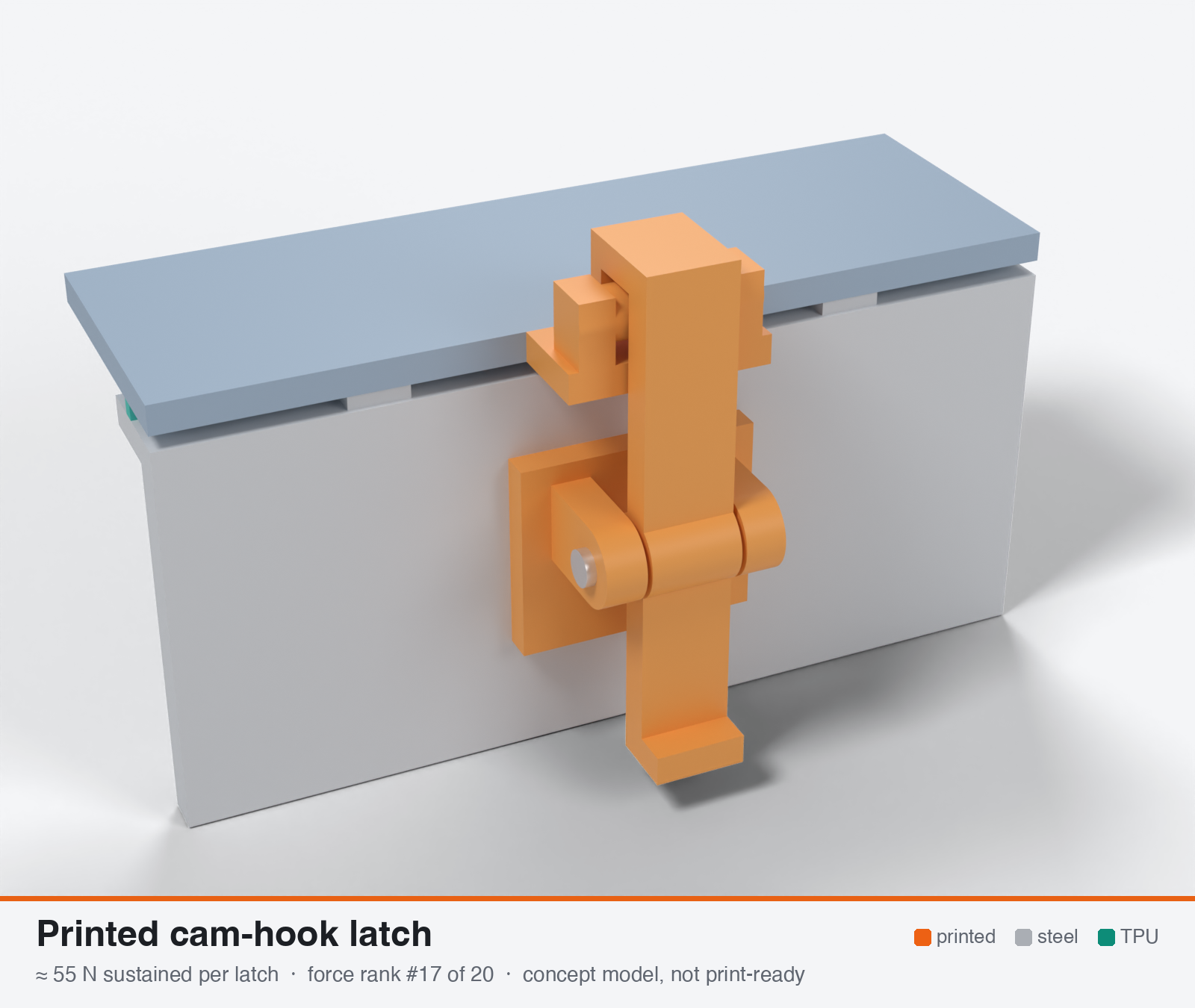
Printed cam-lever hook latch (zx82net / cam-latch-for-boxes style)
- Force rank
- 17 of 20
- Latches for the reference lid
- 26–51
- Build
- Printed + steel hardware
- Hand force to close
- ≈ 12 N
- Adjustable preload
- no
- Positive compression stop
- yes
- Force basis
- estimated
- Review verdict
- corrected
- Confidence
- medium
Verdict: Hook jaw root limited (Winkler curved beam, about 0.075-0.115 MPa/N). Fixed stroke, no spring, and the +/-0.2 mm of FDM tolerance is +/-40-100 % of the force. Fine on small boxes with a light rib. Hot creep takes 40-70 % of the force.
On this page
Parts
Per latch: 2 parts to print, 3 items to buy, 3 features printed into the box or lid and the TPU 85A seal. Parts marked † are not drawn in the 3D model. In the 3D gallery you can click a part to see where it sits. The last column links the print file, or an example of the part in a shop (see the shopping list).
| Part | Qty | Type | What to use | File or shop |
|---|---|---|---|---|
| Mount with ears | 1 | ASA, flat on its back; 4.25 mm bore | mount.stl | |
| Cam-hook lever | 1 | ASA, on its side, 100 % infill | cam-hook-lever.stl | |
| Pivot bolt | 1 | Buy | M4 × 25 stainless screw with an M4 nyloc nut | M4 screw · M4 nyloc |
| Mount screws † | 2 | Buy | M3 × 10 A2/A4 socket screws (DIN 912) | Grobotronics |
| Square nuts † | 2 | Buy | M3 square nuts (DIN 562), dropped down the channels in the box wall | Grobotronics |
| Catch peg | 1 | Printed with the lid | Peg on two posts on the lid tab; an M3 screw in it makes the catch adjustable | lid-coupon.stl |
| Hard stops | 2 | Printed with the box | Pads on the rim either side of the latch, 1.6 mm tall: 0.8 mm below the free seal | box-coupon.stl |
| Nut channels | 2 | Printed with the box | Inside pillar with a 5.7 × 2.0 mm channel per nut, open on the rim outside the seal; blind 3.4 mm screw holes, so no path into the box | box-coupon.stl |
| Seal strip | 1 | Seal (TPU 85A) | TPU 85A, 1.5 × 3.4 mm, in a 1.8 × 1.0 mm groove in the rim; the latch squeezes it 0.8 mm | seal-strip.stl |
Print files
Download all print files for this latch (ZIP, 81 kB)
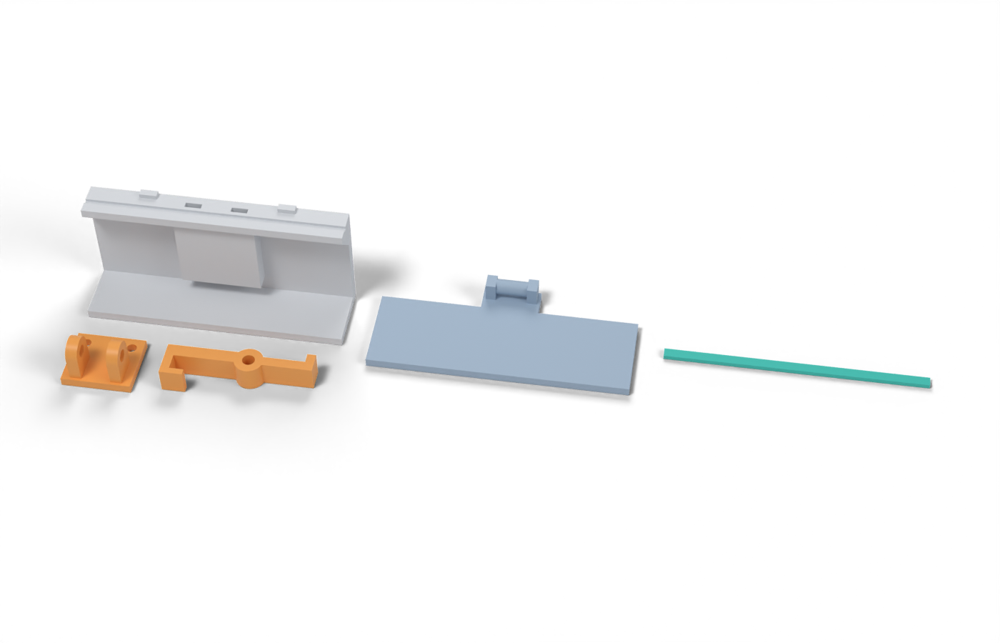
Print in ASA (TPU 85A for the seal), 0.2 mm layers, at least 4 walls; settings and the clearances used are in print/README.md. The parts are already turned the right way up for printing. The box and lid coupons are short test sections with this latch's box-side and lid-side features, so you can try the latch before building it into your own enclosure.
| File | Material | Qty | Size (mm) | How to print |
|---|---|---|---|---|
| mount.stl | ASA | 1 | 24 × 21 × 16.5 | Flat on its back, no supports. 4.25 mm bore for an M4 × 25 bolt with a nyloc nut. 2 × M3 × 10 into the box. |
| cam-hook-lever.stl | ASA | 1 | 50.5 × 15 × 9 | On its side (pin axis vertical), no supports, 100 % infill. |
| box-coupon.stl | ASA | 1 | 90 × 24 × 41.6 | Upright, no supports. A section of box wall with this latch's box-side features: seal groove, hard stops, and an inside pillar with nut channels. Push an M3 square nut down each of the 2 channels in the rim before fitting the screws. Copy these features into your own box. |
| lid-coupon.stl | ASA | 1 | 90 × 39.6 × 9.5 | Flat, top up. A section of lid with this latch's lid-side features. Copy them into your own lid. |
| seal-strip.stl | TPU 85A | 1 | 90 × 3.4 × 1.5 | TPU 85A, 100 % infill, lying on its side. Press it into the rim groove: it stands 2.4 mm proud and the latch squeezes it 0.8 mm, until the lid lands on the hard stops. |
All printed parts in their assembled positions, for CAD: cam-hook-printed.step.
How it works
Two printed parts. A lever with an eccentric cam end pivots on a base pin (M3/M4 screw or steel pin). A hook on the lever engages a catch bar on the lid, and swinging the lever over center pulls the lid down by the cam throw. The final position is a fixed geometric stroke, so force is stroke-controlled: it depends on how stiff the printed chain and the gasket are.
Mechanical advantage
About 8-12:1 (50 mm lever, 4-6 mm effective cam offset including friction). Hand force to close at 80 N clamp is about 8-12 N plus the over-center snap. The ratio is not the limit: the hook section is.
What limits the force
Bending plus tension in the printed hook jaw (curved-beam root) at the long-term in-plane stress for ASA at 60-70 C of about 3-8 MPa. After that, creep of hook and cam, and fixed-stroke tolerance (+/-0.2 mm FDM vs. 0.2-0.75 mm gasket window). Pivot pins are not the limit.
Analyst's calculation
Analyst's sustained estimate: 40–140 N, typical 80 N; peak 450 N.
NO PUBLISHED FORCE TEST for this printed latch type; the web-search tool refused new searches (budget exhausted) and the model pages (Printables, Thingiverse, MyMiniFactory, MakerWorld) returned HTTP 403, so the leak-test and creep-warning statements below are from the brief and are not re-checked. HOOK ROOT (own calc, curved-beam factor 1.3, throat 4.5 mm, load offset from section centroid e = r_in + t/2): sigma/F = 1.3 x (e/Z + 1/A). Jaw b x t = 10x5 mm gives 0.174 MPa per N: 29 N at 5 MPa. b x t = 12x7 mm gives 0.092: 33 N at 3 MPa, 54 N at 5 MPa, 87 N at 8 MPa. b x t = 16x8 mm gives 0.058: 52 N at 3 MPa, 87 N at 5 MPa, 138 N at 8 MPa. The stress levels are the working rule from the brief (3-5 MPa cautious, up to 5-8 MPa optimistic, in-plane ASA at 60-70 C). A typical maker-sized hook (8x5 mm) is 20-40 N. Envelope-filling hook (16x8 mm) gives 40 / 85 / 140 N. SUSTAINED taken as 40 / 80 / 140 N, which matches the 60-150 N maker range in the brief. PIVOT: M4 pin, 2 x 6 mm ears: 48 mm2 x 8-10 MPa = 380-480 N, so not limiting. PEAK: short-term in-plane ASA tension of about 35 MPa over the 16x8 hook gives about 600 N; with stress concentrations and layer faults take 450 N (range 250-600 N). Proxy: CNC Kitchen's printed hook test failed ASA printed lying at 57 kg (about 559 N) and standing at 17 kg (about 167 N) and PETG 55 vs 25 kg (geometry not the same as this hook; https://www.cnckitchen.com/blog/comparing-pla-petg-amp-asa-feat-prusament, fetched and confirmed). PRELOAD RETENTION (own estimate): the chain is rigid, so gasket set (30-58 % at 70 C) is not compensated, plus hook creep. A hook arm 40 mm long at 5 MPa and E about 1.3 GPa at 60 C strains about 0.4 % elastic, and creep may double it: 0.16 mm of lost stroke, similar to the 0.2-0.75 mm gasket window. Expect to keep only 30-60 % of the force after a hot season. COLD: a rigid latch at 80 N at 23 C may see 120-160 N at -20 C (Texin modulus 2.2x), and ASA is brittle (3 kJ/m2 Charpy at -30 C), so set the 23 C preload at 50-60 N. GASKET LINE LOAD: 80 N at 50 mm pitch is 1.6 N/mm, which is just under the 1.7 N/mm needed for Garlock's 1.4 MPa seal stress on a 1.2 mm rib. To get 2.8 kN on the reference lid would need about 20-35 latches. Hand force at 80 N is about 8-12 N.
Adversarial review
Independent recomputation using exact Winkler curved-beam stress for a rectangular hook section (b x t, r_i = 2.25 mm; centroid radius r_c = r_i + t/2; neutral axis r_n = t / ln(r_o/r_i); sigma_i = F r_c (r_n - r_i) / (A e_c r_i) + F/A). Results in MPa/N: 10x5 = 0.199, 12x7 = 0.115, 16x8 = 0.075 (a larger inner radius of 3 mm barely changes it, 0.076). Analyst values of 0.174 / 0.092 / 0.058 are 15-30 % low. Using the same 3/5/8 MPa working rule: 12x7 gives 26/44/70 N and 16x8 gives 40/66/106 N. That is where my 25/55/100 comes from (envelope-filling hook at ~4-5 MPa). Pivot bearing is not limiting (checked 48 mm2 x 6-10 MPa). Texin and CNC Kitchen hook-test numbers confirmed. The CNC Kitchen oven test also confirmed (PLA starts to give at 60 C, PETG 80 C, ASA 110 C; failure ~5-10 C later). The filamentspecs page confirms 11.5 % (PETG) vs 3 % (PLA) preload loss over 7 days but gives no bolt size, torque or temperature and has no ASA data, so it should not be transferred. All printed-design links returned HTTP 403, so existing-design claims stay unverified. WebSearch budget was exhausted, so no extra hot-soak or cam-latch force data could be searched for. Outdoor durability trimmed 5 to 4 because there is no steel spring to absorb creep and set. Printability stays 9 and usability 8 (12 N, one motion).
Issues raised:
- The curved-beam factor of 1.3 is too optimistic for a tight-throat hook. A Winkler solution (inner radius 2.25 mm, load through the centre of curvature, plus direct tension) gives 0.115 MPa/N for a 12x7 hook (analyst 0.092) and 0.075 MPa/N for 16x8 (analyst 0.058), i.e. 25-30 % higher stress. At 3/5/8 MPa the capacity is 26/44/70 N for 12x7 and 40/66/106 N for 16x8, so typical drops from 80 to ~55 N and high from 140 to ~100 N.
- Peak: 35 MPa ASA in-plane at the inner fibre gives 305 N (12x7) to 465 N (16x8). With layer faults and notch effects I use 350 N (range 200-550). The CNC Kitchen hook failing at 559 N is a different geometry, so it is only a loose proxy.
- Fixed-stroke force is unpredictable. The printed lever/hook chain has stiffness of the same order as the gasket (~100-400 N/mm vs 336 N/mm at 30 mm pitch), so +/-0.2 mm FDM tolerance is +/-20-80 N, i.e. +/-40-100 % of the 55 N typical. With no spring and no adjustment, some latches leak and others overload the hook. This is the main reason it ranks last on seal suitability.
- Preload retention: no steel in the load path, so gasket set (30-58 % at 70 C) and ASA creep at 4-8 MPa both come straight out of the force. The 'keeps 30-60 %' figure is a guess. Cold gives 1.5-2x (modulus 26.9 to 59.0 MPa, verified), and 55 N at 23 C may reach 80-110 N at -20 C next to a brittle ASA hook root.
- Requirement mismatch: 55 N at 30 mm pitch = 1.8 N/mm, but at 50 mm pitch it is only 1.1 N/mm, below the 1.7 N/mm needed for the 1.4 MPa Garlock threshold on a 1.2 mm rib. The 700 mm reference lid would need ~25-50 latches. Only useful on small boxes (perimeter below ~300 mm) with a light rib.
- None of the five printed-design pages (MyMiniFactory, Thingiverse, Printables 355435, MakerWorld 87535, MakerWorld 454290) could be opened. The 10 cm / 10 min dunk test and 'PETG not PLA' creep warning are therefore brief-only hearsay. The dunk test used a soft cord/TPU seal at low load, which does not show sealing at the 1.7-4 N/mm line load.
- Pivot and ear bearing (M4, 2x6 mm = 48 mm2, 288-480 N at 6-10 MPa) is correctly not the limit. The analyst's statement about the hook root and layer orientation (print lying flat, pin along Z) is right and matches the CNC Kitchen lying/standing ratio (ASA 57 vs 17 kg = 30 %, PETG 55 vs 25 kg = 45 %).
Preload retention outdoors
Poor. Fixed stroke, no spring and no adjustment, so gasket compression set (30-58 % loss at 70 C) and hook/cam creep (PETG and PLA creep more; designer warns PLA loosens the seal) both go straight into lost force. Expect 30-60 % of the original force left after a hot season. Cold has the opposite effect: force rises 1.5-2x at -20 C.
Materials
ASA (default), 100 % infill on the lever and hook. UV-stabilised PC probably raises the sustained limit by 1.3-1.5x (own judgement). PETG is marginal at 60-70 C. PLA is unsuitable (creeps, fails near 60-65 C). PETG-CF has HDT 68 C, so the carbon fibre does not help heat.
Hardware notes from the research
M3 or M4 stainless screws and nuts or heat-set inserts as pivots (optionally a 4 mm stainless pin), optional M3 stainless set screw as adjustable catch, TPU 85A gasket. Optional stainless torsion or leaf spring to give a small spring preload.
Design guidelines
- Print the lever and hook lying flat so layers run in the plane of the hook, pin axis along Z. Use 100 % infill, 4+ perimeters and 0.2 mm layers or finer for the lever and the catch.
- Make the hook jaw at least 12x7 mm (16x8 mm if the envelope allows). Throat radius 2.5 mm min. Use 2 mm fillets at the hook root and avoid sharp inside corners, since ASA is notch-sensitive in the cold.
- Use steel pins or M4 screws through bushed holes. Pivots are not the limit at 80 N, but a steel pin avoids wear.
- Keep the 23 C preload at 50-60 N or less so the cold peak (1.5-2x) stays within the hook limit. Do not rely on the lever force to compress the gasket: fit a printed hard stop beside the latch at about 0.75-0.8 x free bead height.
- Add an adjustable catch (M3 or M4 set screw or eccentric) if you need to compensate for +/-0.2 mm FDM tolerance and compression set. Without it, expect large latch-to-latch variation.
- Add a detent bump on the cam so it cannot back off. Use a thin TPU or steel spring clip for outdoor vibration.
- Latch pitch 30-50 mm for a flat 3 mm lid edge (rim limit about 28 mm), because 80 N at 50 mm is only 1.6 N/mm. Stiffen the rim with a skirt before adding more latches.
- Use small boxes (perimeter below about 400 mm) and a light gasket (1.2 mm rib, 1.7-2 N/mm), or combine with an adjustable stud design for larger lids.
Failure modes
- Hook jaw creeps open or cracks along layer lines at 60-70 C because it carries bending plus tension at 3-8 MPa.
- Cam surface creeps or flat-spots so the lever backs off and the seal loosens.
- Fixed stroke: tolerance spread of +/-0.2 mm swings the force from near zero to the limit. Some latches leak, others overload.
- Cold overload: force rises 1.5-2x at -20 C and ASA is brittle near -30 C, so the hook root cracks.
- Not enough total force: 40-140 N per latch is well under the 233-467 N per latch needed on the reference lid.
- Over-center lever springs open in vibration if there is no detent.
Existing designs and commercial references
- zx82net Customizable Rugged Waterproof Box (MyMiniFactory) — Cam latch, TPU or cord seal. Per brief: reviewer submerged it 10 cm for 10 min, dry with thick seal, about 10 ml in with thin seal. Page returned 403 to my fetch; not verified.
- zx82net box (Thingiverse 3338826) — Per brief: designer recommends PETG over PLA since PLA creeps. 403 to my fetch; not verified.
- Cam latch for boxes (Printables 355435) — Per brief: M4 mounting, 100 % infill on the latch, locking arms break first. 403 to my fetch; not verified.
- Cam latch for boxes, stronger remix (MakerWorld 87535) — Stronger-cam remix per brief; not verified.
- Waterproof Box (MakerWorld 454290) — Cam latch plus printed TPU or silicone seal, 8x M3x20, 3 perimeters >30 % infill, tested PLA/PETG only per brief. 403 to my fetch; not verified.
Evidence gathered in the sweep
SUSTAINED (own est., ASA, M4 pivots): 60-150 N (maker 60-150 N; industrial 50-200 N); PEAK 250-600 N. No force or pull-off test published. SEAL TEST: reviewer submerged zx82net box 10 cm for 10 min, dry with thick seal, ~10 ml in with thin seal https://www.myminifactory.com/object/3d-print-zx82net-customizable-rugged-waterproof-box-146437 ; designer recommends PETG over PLA because PLA creeps and loosens the seal https://www.thingiverse.com/thing:3338826 ; MakerWorld Waterproof Box (cam latch, printed TPU seal or silicone, 8x M3x20, 3 perimeters >30 % infill, tested in PLA/PETG only) https://makerworld.com/en/models/454290-waterproof-box ; Printables cam latch for boxes: 100 % infill on moving latch part, locking arms break first https://www.printables.com/model/355435-cam-latch-for-boxes ; stronger-cam remix https://makerworld.com/en/models/87535-cam-latch-for-boxes . Same family: Instructables/MakerWorld printed toggle clamps and cam F clamps (no force data). CONFIDENCE: low.
Sources
- CNC Kitchen: ASA/PETG/PLA hook tests and oven test — Fetched and confirmed: lying vs standing hook failure loads; PETG softens 80 C, ASA 110 C.
- Creep resistance of 3D printed parts (FilamentSpecs) — Fetched and confirmed: bolted joint preload loss about 11.5 % PETG vs about 3 % PLA over 7 days (do not transfer to other sizes).
- zx82net box (MyMiniFactory) — From the brief. Not verified (403).
- zx82net box (Thingiverse 3338826) — From the brief. Not verified (403).
- Texin 985 datasheet — From the brief. Gasket line load and cold modulus.
Sources the reviewer flagged (dead, blocked or misdescribed):
- https://www.myminifactory.com/object/3d-print-zx82net-customizable-rugged-waterproof-box-146437 - HTTP 403 to me too; dunk-test numbers unverified.
- https://www.thingiverse.com/thing:3338826 - HTTP 403; PETG-over-PLA creep advice unverified.
- https://www.printables.com/model/355435-cam-latch-for-boxes - HTTP 403; M4 mounting / 100 % infill / 'locking arms break first' unverified.
- https://makerworld.com/en/models/87535-cam-latch-for-boxes - HTTP 403; 'stronger cam' claim unverified.
- https://makerworld.com/en/models/454290-waterproof-box - not re-tested; analyst reports 403.
- https://filamentspecs.com/creep-resistance-3d-printed-parts/ - numbers confirmed but the page gives no bolt size, torque or temperature and no ASA data; not transferable to a hook or cam.