No. 04 of 20 · Baseline, not a latch
Plain lid screws (baseline)
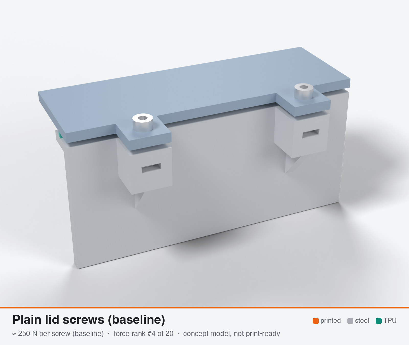
Baseline: lid screws into heat-set inserts or captive nuts
Baseline, not a latch. This is the number every latch has to beat.
Model note: The 3D model and parts list use M3 screws into M3 square nuts pushed into side slots in the bosses, not the heat-set inserts the force estimate is based on. In CNC Kitchen's PETG pull-out test a nut in a side slot held 86 kg, a heat-set insert 119 kg and a nut in a pocket on the far side 166 kg.
- Force rank
- 4 of 20
- Rank for outdoor sealing
- 7
- Build
- Printed + steel hardware
- Hand force to close
- ≈ 17 N
- Adjustable preload
- yes
- Positive compression stop
- yes
- Force basis
- measured
- Review verdict
- corrected
- Confidence
- medium
Verdict: The benchmark any printed latch must beat. Limited by insert pull-out and the washer seat in a hot boss. Durable and printable, with an inherent stop, but rigid, so 35-55 % of the force is lost after hot sun until re-tightened. Usability 3.
Why it ranks #7 for sealing: Reference to beat, not a latch: about 250 N per screw with the best durability (8) and printability (9) and an inherent stop. Rigid, so 35-74 % of the force is lost in hot sun until re-tightened, and cold raises the force about 2x. A steel compression sleeve and a spring washer or stack are the cheap upgrades. Usability 3 (6-11 screws).
On this page
Parts
Per screw: 3 items to buy, 3 features printed into the box or lid and the TPU 85A seal. Parts marked † are not drawn in the 3D model. In the 3D gallery you can click a part to see where it sits. The last column links the print file, or an example of the part in a shop (see the shopping list).
| Part | Qty | Type | What to use | File or shop |
|---|---|---|---|---|
| Screw | 1 | Buy | M3 × 14 A2/A4 socket screw (DIN 912) | Grobotronics |
| Square nut | 1 | Buy | M3 square nut (DIN 562), pushed into the side slot in the boss | Grobotronics |
| Washer † | 1 | Buy | M3 stainless washer, 9 mm across (DIN 9021) if you can get it | Inox Store |
| Screw boss | 1 | Printed with the box | 12 mm wide; the nut slot (5.7 × 2.0 mm) opens on the outside, with 4 mm of plastic above the nut; 100 % infill | box-coupon.stl |
| Lid tab with clearance hole | 1 | Printed with the lid | 3.4 mm hole, counterbored 9.6 × 0.8 mm for the washer | lid-coupon.stl |
| Hard stops | 2 | Printed with the box | Pads on the rim either side of the latch, 1.6 mm tall: 0.8 mm below the free seal | box-coupon.stl |
| Seal strip | 1 | Seal (TPU 85A) | TPU 85A, 1.5 × 3.4 mm, in a 1.8 × 1.0 mm groove in the rim; the latch squeezes it 0.8 mm | seal-strip.stl |
Print files
Download all print files for this screw (ZIP, 45 kB)
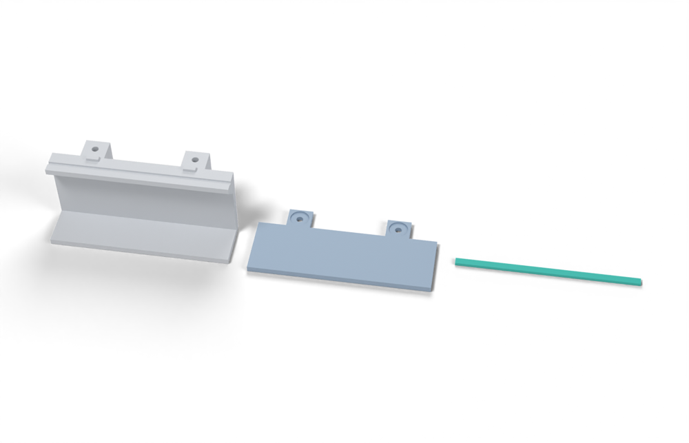
Print in ASA (TPU 85A for the seal), 0.2 mm layers, at least 4 walls; settings and the clearances used are in print/README.md. The parts are already turned the right way up for printing. The box and lid coupons are short test sections with this latch's box-side and lid-side features, so you can try the latch before building it into your own enclosure.
| File | Material | Qty | Size (mm) | How to print |
|---|---|---|---|---|
| box-coupon.stl | ASA | 1 | 90 × 35 × 41.6 | Upright, no supports. A section of box wall with this latch's box-side features: seal groove, hard stops. Copy these features into your own box. |
| lid-coupon.stl | ASA | 1 | 90 × 41 × 3 | Flat, top up. A section of lid with this latch's lid-side features. Copy them into your own lid. |
| seal-strip.stl | TPU 85A | 1 | 90 × 3.4 × 1.5 | TPU 85A, 100 % infill, lying on its side. Press it into the rim groove: it stands 2.4 mm proud and the latch squeezes it 0.8 mm, until the lid lands on the hard stops. |
All printed parts in their assembled positions, for CAD: baseline-screws.step.
How it works
A steel M3/M4 screw with a hardened washer pulls the lid into a brass heat-set insert (or a nut in a bottom pocket) in a printed boss. Preload is set by tightening torque and held by thread friction, so it self-locks and can be re-tightened. The steel is never the weak link. The boss around the insert and the washer seat on the lid are. Adding a metal compression-limiter sleeve moves the clamp load into steel and makes the squeeze a fixed dimension.
Mechanical advantage
Screw thread: M3 pitch 0.5 mm, M4 pitch 0.7 mm. Ideal MA = 2pir/p = 157 for M3 at a 12.5 mm screwdriver-handle radius. With the nut-factor relation F = T/(Kd), K ~0.2 (own assumption), the effective hand-to-preload ratio is about 20:1 (17 N at 12.5 mm radius gives ~0.21 Nm, ~350 N on M3). Self-locking.
What limits the force
Printed boss and washer bearing seat, not the screw. Insert pull-out in the printed boss caps the peak at ~1.17 kN (PETG, 23 C). The sustained limit is the plastic bearing/pull-out stress at 60-70 C, so the practical limit is about 350 N per screw. Preload also decays over days to weeks: gasket compression set and plastic creep remove roughly 35-55 % of a fixed-travel preload after hot sun unless a spring is added or the screw is re-tightened.
Analyst's calculation
Analyst's sustained estimate: 250–500 N, typical 350 N; peak 1170 N.
[Web search budget was exhausted this run, so no new targeted searches were possible. I re-fetched and confirmed the CNC Kitchen, filamentspecs and Hackaday pages; other inputs come from the brief.]
- Washer bearing area (assumed hardware): M3 with DIN 9021 washer, OD 9 / ID 3.4 mm: 54 mm2. M4 with ISO 7089 washer, OD 9 / ID 4.3 mm: 49 mm2. Use ~50 mm2.
- Bearing limit under the washer (compression normal to layers, bearing allowable 5-10 MPa at 60-70 C per the brief's working rule): 50 mm2 x 5 / 7 / 10 MPa = 250 / 350 / 500 N.
- Insert pull-out, MEASURED (CNC Kitchen, PETG, M3, 4 perimeters, 100 % infill, n=3, hole axis along Z, i.e. the pessimistic orientation): Ruthex insert 119 kg = 1167 N, torque-out 3 Nm. Direct screw 118 kg (1158 N), strip torque 1 Nm. Helicoil 120 kg. Side-pocket nut 86 kg = 844 N. Bottom-pocket nut 166 kg = 1628 N. SF 2 on the insert: 583 N at 23 C. Hot derate 0.5-0.7 (own judgement, PETG is near its HDT of 68 C; ASA should do better): 290-410 N. Side-pocket nut with SF 2: 420 N.
- Steel: M3 class 8.8 proof 2.92 kN, M4 5.10 kN. Not limiting.
- Result: peak = 1170 N (insert pull-out). Sustained 250 / 350 / 500 N. The low value is cautious plastic stress in hot ASA or PETG. The high value needs a large washer or sleeve, ASA or PC, and a bottom-pocket nut or deep insert.
- Torque needed: T = KFd = 0.2 x 350 N x 3 mm = 0.21 Nm (M3), or 0.28 Nm (M4). This is far below the 3 Nm insert torque-out. A hand on a 12.5 mm handle radius needs ~17 N.
- Preload retention (own calc). Chain stiffness excluding the gasket: lid under washer 1.8 GPa x 50 mm2 / 4 mm = 22 kN/mm, boss annulus 1.8 GPa x 59 mm2 / 8 mm = 13 kN/mm, steel screw 126 kN/mm. In series this is ~8 kN/mm. Design-rib gasket, 3 N/mm over a 100 mm pitch at 0.48 mm squeeze: ~0.63 kN/mm secant. Loss = set x km/(kg+km) = 0.93 x set. Compression set 16-19 % at 23 C (Texin) gives ~15-18 % loss. Set at 70 C of 35 % (Elastollan C85A55) to 52 % (Ultrafuse) gives ~33-48 % loss. Plastic creep adds on top: PETG bolted joints lost 11.5 % preload in 7 days at room temperature against 3 % for PLA (filamentspecs).
- Cold: with the screw position fixed, force scales with the series stiffness. Gasket modulus x2.2 at -30 C gives ~2.0x the closing force (own calc), so do not set preload at the hot end of the range.
- Fit to the requirement: 350 N typical equals 100 mm pitch x 3.5 N/mm. With a 2.8 kN total this means 8 latches at typical capacity and 6 latches only at the high end.
Adversarial review
Independent recalculation. Hand force: M3 at 0.21 Nm is 17 N at 12.5 mm radius, checked. K = 0.2 gives 350 N, but the correct preload for this boss is ~250 N, i.e. about 0.15 Nm. Washer area (OD 9 / ID 3.4): 54 mm2, checked. Joint stiffness chain: lid 22.5, boss 13.3, screw 126 kN/mm in series gives 7.8 kN/mm, checked. Gasket secant 300 N / 0.48 mm = 0.625 kN/mm, so loss = 0.93 x set, checked. Hold-down count: 2.8 kN / 250 N = 11 screws at 63 mm pitch, which is fine against rim bending only if the rim is stiffened. At the 8-latch reference the screws cover the low load window (175 N each) but not the high one (350 N each). Sources opened: CNC Kitchen PETG insert page confirmed (118/119/120 kg, side nut 86, bottom nut ~166, torque-out 1/3/1/2 Nm, n=3 pull-out, 4 perimeters 100 % infill). CNC Kitchen cheap-vs-expensive page confirmed (Ruthex 181, eBay 157, cheap 39, direct 142 kg PLA; shallow-knurl eBay insert rotated in ASA). CNC Kitchen datasheet page confirmed (~1400 N, 4.2 mm CAD hole, knurl OD ~4.6 mm). Optimas confirmed (M3 2.92, M4 5.10, M5 8.23 kN). Texin 985 PDF decoded locally and confirmed (D575 table, set 16/19 % at 23 C, 40/80 % at 70 C, flexural 26.9 vs 59.0 MPa, Vicat 80 C). Ultrafuse TDS confirmed (26 % and 52 %). Elastollan C85A55 confirmed (25 % and 35 %, Vicat 110 C). Hackaday log confirmed in substance, but it is a PLA profiler cap/collar with eye bolts, not a lid. CNC Kitchen carbon-nylon page: no ASA re-tighten count, only 'PA12 once, similar to PLA and ASA', so the analyst's own caveat is right. No new web searches were possible (search budget exhausted); all checks used WebFetch and local PDF decoding.
Issues raised:
- Sustained 350 N typical is too high. It takes the PETG/23 C insert pull-out (1167 N), halves it for SF 2, then applies only a 0.5-0.7 hot derate. That skips two factors the brief's own working rule includes: ASA delaminates earlier than PETG (standing hook 17 vs 25 kg, ratio 0.68) and long-term creep. The brief's rule (3-5 MPa against ~40 MPa short term) is a total factor of about 0.12. Applied to 1167 N it gives about 100-200 N for an M3 insert. The washer-bearing check is fine and not limiting (50 mm2 x 8-10 MPa = 400-500 N).
- Insert-limit cross-check: the M3x5.7 Ruthex has a knurl OD of ~4.6 mm, so ~80 mm2 of lateral area. 1167 N is ~14 MPa average at room temperature. At a 2-3 MPa hot sustained allowable that is 160-250 N. An M4x8 insert has about 1.7x the area, so ~300-430 N. Typical 250 N is a compromise. A rigid screw is displacement-controlled, so creep relaxes the preload instead of rupturing the boss, which supports the upper end.
- Peak 1170 N is a measured number for a different object: an insert in a flat PETG test bar at 23 C, n=3, not a latch and not ASA. Using ASA/PETG = 0.68-1.0 gives 800-1170 N, so 900 N is a safer figure. The 'measured' label applies to the component only, not to the latch.
- Claim 'hole axis along Z, i.e. the pessimistic orientation' is not on the cited CNC Kitchen pages. Both the PETG helicoil page and the PLA insert pages leave the pull-out orientation unstated (the PETG page says only 'flat test pieces, 4 perimeters, 100 % infill'). Treat the orientation as inferred, not tested.
- The 11.5 % PETG vs 3 % PLA preload loss is second-hand. filamentspecs takes it from the control groups of an MDPI Polymers 2021 accelerated-aging study (compression creep). The page states no bolt size, torque or temperature. 'Bolted joints at room temperature' is the analyst's gloss, and MDPI returned HTTP 403, so the primary was not checked.
- Preload-loss range is truncated at the hot end. It uses Elastollan 35 % and Ultrafuse 52 % set at 70 C, but the brief's Texin 985 sheet (re-read) gives 40 % and 80 % at 70 C/22 h. A rigid joint can therefore lose 33-74 %, not 33-48 %. Retained force after hot sun without a re-tighten is roughly 25-65 % of the assembly preload. The 250 N figure is capacity at assembly, not what is still clamping in August.
- Torque-controlled preload scatters about +/-30 % because the nut factor K is assumed at 0.2 (real range 0.15-0.3). Without a metal sleeve there is no hard stop, so the 'positive compression stop = true' flag only holds with the sleeve.
- Seal score cut from 7 to 6: the rigid joint loses most of its force in hot sun and needs a re-tighten routine, and the preload scatter is large. Usability 3 stands (6-11 screws to open).
Preload retention outdoors
Poor to fair for the fixed rigid joint. Expect ~15-18 % loss after cool-weather settling and ~35-55 % after hot sun (gasket set at 70 C plus plastic creep), mostly in the first days. A re-tighten after the first hot cycle restores it, and later losses are smaller as the gasket set saturates. TPU stress relaxation is not included (unmeasured). A steel compression sleeve stops the plastic seat creeping but does not stop gasket set.
Materials
ASA is the default for the boss and lid flange. UV-stabilised PC probably raises the sustained limits ~1.3-1.5x (own judgement, unmeasured). Avoid PETG for sustained load at 60-70 C: HDT 68 C and 11.5 % preload loss in a week at room temperature. Avoid PA6-CF outdoors (3.33 % water uptake, -22 % XY strength). PAHT-CF is acceptable but still creeps.
Hardware notes from the research
Flagged: the screw, insert and washer are not printed. A2/A4 stainless M3-M4 pan or cap screws, brass heat-set inserts (Ruthex-type with deep knurling) or A2 nuts in bottom pockets, A2/A4 DIN 9021 washers, and optional stainless or brass compression-limiter sleeves. The positive stop only holds with the sleeve or a printed standoff.
Design guidelines
- Boss: OD >= 12 mm for M3 and >= 14 mm for M4. Keep >= 3 mm of wall around the insert, which is 7-8 perimeters of 0.4 mm. Use 100 % infill in the boss and 4+ perimeters elsewhere. Tie the boss to the wall with 2-3 ribs of 1.6-2 mm and a root fillet R >= 2 mm.
- Print the boss with its hole axis along Z. This is the orientation CNC Kitchen tested (119 kg in PETG), and it gives round holes. Do not rely on a horizontal-axis boss.
- Insert hole: follow the maker's sheet. For Ruthex M3 use 4.0 mm drilled, or ~4.2 mm in CAD for an as-printed hole (printed holes come out 0.1-0.25 mm small). Print a calibration coupon per printer and material. Leave 2-3 mm of blind depth below the insert. Melt in at 210-240 C and press flush with a straightener.
- Choose inserts with deep knurling. CNC Kitchen saw a shallow-knurl eBay insert rotate in softer ASA.
- Lid hole: 3.4 mm clearance for M3 and 4.5 mm for M4, counterbored for a washer with OD >= 9 mm. Fit a stainless or brass compression sleeve of length = flange thickness minus the design squeeze. This gives a hard stop beside each screw. Also add a printed stop at 0.75-0.8x the free bead height.
- Set the torque limit to 0.3 Nm for M3 and 0.4-0.5 Nm for M4 (~400-500 N). Never use the direct-screw strip torque (1 Nm) as a target. Re-tighten after the first hot day and again after the first week.
- Place the screws outside the gasket line, or add an O-ring or sealing washer if they sit inside it. A through-hole in the lid is a leak path.
- Screw pitch is set by rim bending, not by screw strength: ~28 mm on a flat 3 mm lid edge, ~110 mm with a 20 mm skirt (brief's calc). Stiffen the rim before adding screws.
- Add a 2-3 mm chamfer or fillet at every internal corner. ASA is brittle at -30 C (3 kJ/m2 notched).
Failure modes
- Insert pull-out or layer delamination in the boss under hot sustained load.
- Layers split under bolt and washer clamping. A bolt-clamped PLA lid did this in the Hackaday log.
- Washer indents into the lid flange and preload is lost.
- Preload decays from gasket compression set and plastic creep. This is the main field failure.
- Over-torque strips the direct-screw version at ~1 Nm.
- Water enters through the lid screw hole.
- The boss root cracks in the cold at sharp corners.
- Zinc-plated hardware rusts (12-72 h salt spray). Use A2/A4 stainless.
- Users leave screws loose.
Existing designs and commercial references
- Hackaday.io project 12125, log 41900: PLA instrument housing with bolt-clamped lid — Cautionary example. The printed layers split under bolt and washer clamping and the author tried an epoxy coating. Not a sealed or outdoor design. Verified by fetch.
Evidence gathered in the sweep
SUSTAINED (own est.): 300-500 N per M3/M4 screw with washer (30-50 mm2 bearing at ~10 MPa); SF 2 on the PETG M3 insert peak gives ~580 N at 23 C before any hot derate (own calc). PEAK: ~1.2 kN (insert pull-out). MEASURED (CNC Kitchen, PETG M3, flat bar, 4 perimeters, 100 % infill, n=3): Ruthex insert 119 kg (~1.17 kN) pull-out, 3 Nm torque-out; direct screw 118 kg but 1 Nm strip torque; Helicoil 120 kg; side-pocket nut 86 kg (~840 N); bottom-pocket nut ~166 kg (~1.63 kN) https://www.cnckitchen.com/blog/helicoils-threaded-insets-and-embedded-nuts-in-3d-prints-strength-amp-strength-assessment . PLA M3: Ruthex 181 kg, eBay insert 157 kg, cheap moulded insert 39 kg https://www.cnckitchen.com/blog/threaded-inserts-for-3d-prints-cheap-vs-expensive . Hole sweep: ~1.4 kN average at 3.6 mm hole in PLA https://www.cnckitchen.com/blog/are-our-heat-set-insert-datasheets-wrong . M4 bolt creep, 1 week at room temp: ASA and PLA ~1 re-tighten https://www.cnckitchen.com/blog/carbon-fiber-nylon-in-3d-printing-pa6-vs-pa12-tested ; PETG joints lost 11.5 % preload in 7 days https://filamentspecs.com/creep-resistance-3d-printed-parts/ . Printed lid layers split under bolt clamping (PLA instrument housing) https://hackaday.io/project/12125/log/41900 . Insert white paper (provenance unclear) M3/M4/M5 1.3/2.7/3.4 kN, low confidence. No hot (60-70 C) or sustained data. CONFIDENCE: medium at 23 C, low when hot.
Sources
- CNC Kitchen: helicoils, threaded inserts and embedded nuts (PETG M3) — Verified by fetch: 118/119/120 kg direct/Ruthex/Helicoil, side-pocket nut 86 kg, bottom-pocket ~166 kg, torque-out 1/3/1/2 Nm, 4 perimeters 100 % infill.
- CNC Kitchen: threaded inserts, cheap vs expensive (PLA M3) — Verified by fetch: Ruthex 181 kg at 4.0 mm, eBay 157 kg, cheap moulded 39 kg, direct screw 142 kg. Torque-out 3-4 Nm for inserts, ~1 Nm direct. Shallow-knurl insert rotated in ASA.
- CNC Kitchen: are our heat-set insert datasheets wrong? — Verified by fetch: ~1400 N average at 3.6 mm hole (PLA). About 4.2 mm CAD recommended for as-printed M3 holes. Printed holes ~0.25 mm small.
- filamentspecs: creep resistance of 3D printed parts — Verified by fetch: bolted-joint preload loss ~11.5 % PETG vs ~3 % PLA in 7 days. Bolt size, torque and temperature are not stated on the page.
- CNC Kitchen: carbon fiber nylon, PA6 vs PA12 tested (bolt creep) — Verified by fetch: M4 at 0.8 N*m, ~1 week. PA6 needed re-tightening almost daily and PA12 once. The page says PA12 behaved like PLA and ASA but gives no ASA-specific count, so the brief's 'ASA ~1 re-tighten' is comparative only.
- CNC Kitchen: comparing PLA, PETG and ASA (Prusament) — Verified by fetch: hook test lying/standing PLA 73/40 kg, PETG 55/25 kg, ASA 57/17 kg. Oven: PETG fails ~85 C, ASA ~120 C.
- Optimas: ISO metric thread proof loads — From brief, not re-fetched. M3/M4/M5 class 8.8 proof 2.92/5.10/8.23 kN.
- Texin 985 datasheet (TPU 85A compression set) — From brief, not re-fetched. Compression set 16-19 % at 23 C and 40-80 % at 70 C.
Sources the reviewer flagged (dead, blocked or misdescribed):
- https://www.cnckitchen.com/blog/helicoils-threaded-insets-and-embedded-nuts-in-3d-prints-strength-amp-strength-assessment : numbers correct, but the pull-out orientation (hole axis along Z) is not stated on the page
- https://filamentspecs.com/creep-resistance-3d-printed-parts/ : 11.5 % / 3 % are secondary figures from an MDPI Polymers 2021 aging study (compression creep, controls); the page gives no bolt size, torque or temperature, so 'bolted joint at room temperature' is not supported
- https://www.mdpi.com/2073-4360/13/23/4132 : HTTP 403, primary for the 11.5 % figure not checked
- https://www.cnckitchen.com/blog/carbon-fiber-nylon-in-3d-printing-pa6-vs-pa12-tested : gives PA12 one re-tighten and PA6 near-daily; no ASA count, so the brief's 'ASA about one re-tighten' is only comparative
- https://hackaday.io/project/12125/log/41900 : the part is a PLA cap/collar with eye bolts, not a bolt-clamped lid