No. 03 of 20 · Rectangular lids
Swing bolt + knob/wing nut
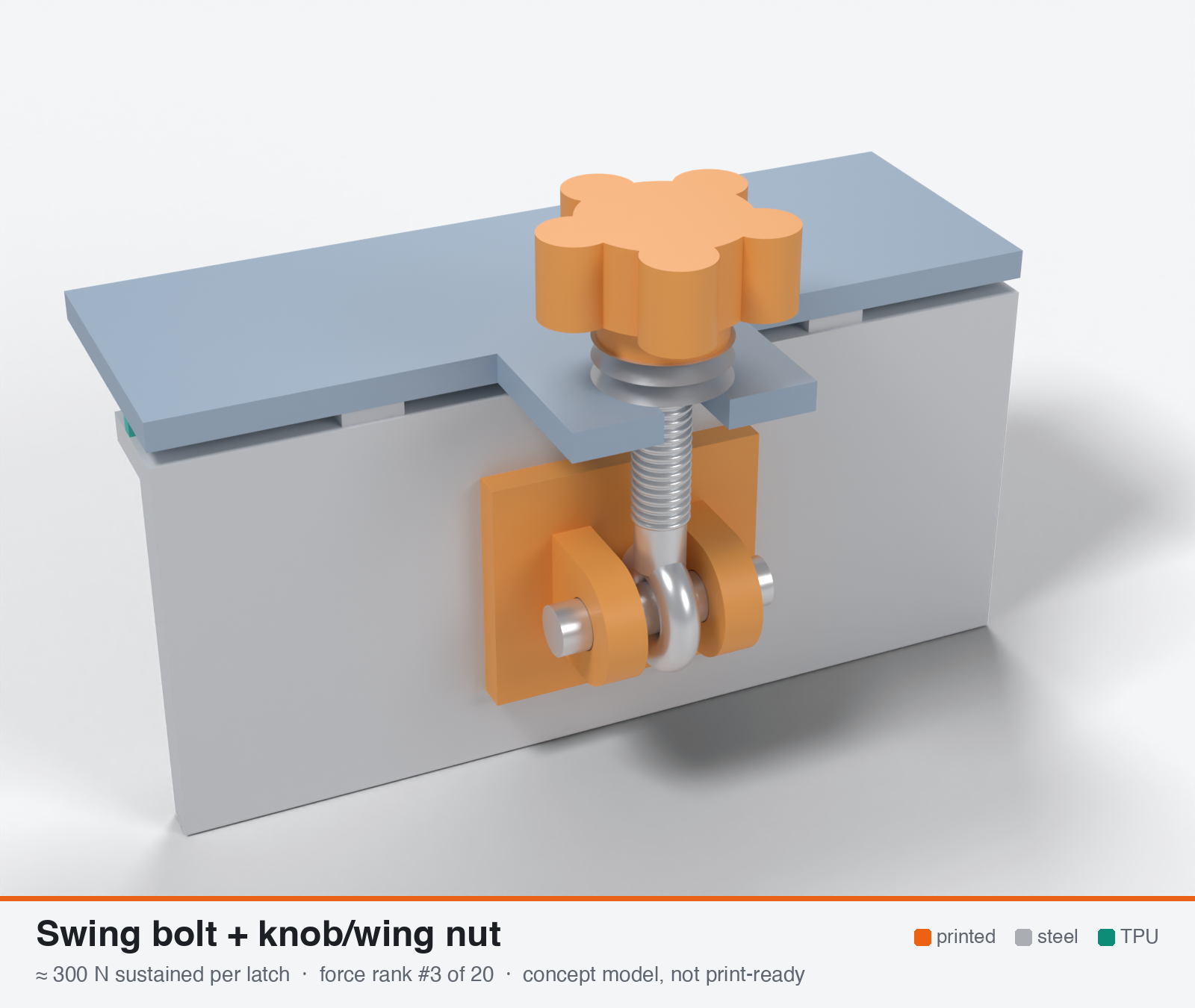
Swing bolt / eye bolt with wing nut or knob in a printed clevis
- Force rank
- 3 of 20
- Rank for outdoor sealing
- 2
- Latches for the reference lid
- 5–10
- Build
- Printed + steel hardware
- Hand force to close
- ≈ 14 N
- Adjustable preload
- yes
- Positive compression stop
- no
- Force basis
- calculated
- Review verdict
- corrected
- Confidence
- low
Verdict: Cut from 400 N because the clevis bracket anchors to the wall like a baseline screw and adds a pin joint. Torque is set by the hand, so a Belleville stack or torque-limiting knob is needed. Fully re-tensionable, but slow to operate.
Why it ranks #2 for sealing: About 300 N sustained (range 200-450). A steel eye-bolt with a washer or Belleville stack gives the highest force among the fully recoverable closures, and it can be re-tightened after the first hot week. Use an A2/A4 DIN 444 bolt, not the zinc 4.6 version. Print the clevis flat as a separate bracket, because an integral upright clevis tears at about 340 N or less. Limit torque with a small knob or slip clutch. Usability 4 (several turns each).
On this page
- Parts
- Print files
- How to assemble
- How it works
- Mechanical advantage
- What limits the force
- Analyst's calculation
- Adversarial review
- Calibration adjustments
- Preload retention outdoors
- Materials
- Hardware notes from the research
- Design guidelines
- Failure modes
- Existing designs and commercial references
- Evidence gathered in the sweep
- Sources
Parts
Per latch: 2 parts to print, 7 items to buy, 3 features printed into the box or lid and the TPU 85A seal. Parts marked † are not drawn in the 3D model. In the 3D gallery you can click a part to see where it sits. The last column links the print file, or an example of the part in a shop (see the shopping list).
| Part | Qty | Type | What to use | File or shop |
|---|---|---|---|---|
| Clevis bracket | 1 | ASA, flat on its back; ears 7 mm thick, 5.2 mm bore | clevis-bracket.stl | |
| Knob | 1 | ASA, upside down; hex pocket for the nyloc nut | knob.stl | |
| Bracket screws † | 4 | Buy | M3 × 10 A2/A4 socket screws (DIN 912) | Grobotronics |
| Square nuts † | 4 | Buy | M3 square nuts (DIN 562), dropped down the channels in the box wall | Grobotronics |
| Hinge bolt | 1 | Buy | M5 × 30 stainless screw with an M5 nyloc nut | M5 screw · M5 nyloc |
| Swing bolt | 1 | Buy | M5 × 50 A2/A4 eye bolt (DIN 444); the eye at most 13 mm across and 7.5 mm thick | Schraubenhandel24 |
| Knob nut † | 1 | Buy | M5 A2/A4 nyloc nut, pressed into the knob | Grobotronics |
| Disc springs | 4 | Buy | Stainless disc springs for M5 (DIN 2093, 10 × 5.2 mm); keep the force up as the seal creeps (optional, recommended) | RVS Edelstahl |
| Washer † | 1 | Buy | M5 stainless washer, 15 mm across (DIN 9021) if you can get it; spreads the load on the lid tab | Inox Store |
| Slotted lid tab | 1 | Printed with the lid | Slot 6.4 mm wide with a flat seat | lid-coupon.stl |
| Hard stops | 2 | Printed with the box | Pads on the rim either side of the latch, 1.6 mm tall: 0.8 mm below the free seal | box-coupon.stl |
| Nut channels | 4 | Printed with the box | Inside pillar with a 5.7 × 2.0 mm channel per nut, open on the rim outside the seal; blind 3.4 mm screw holes, so no path into the box | box-coupon.stl |
| Seal strip | 1 | Seal (TPU 85A) | TPU 85A, 1.5 × 3.4 mm, in a 1.8 × 1.0 mm groove in the rim; the latch squeezes it 0.8 mm | seal-strip.stl |
Print files
Download all print files for this latch (ZIP, 0.1 MB)
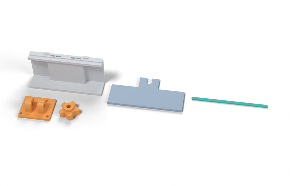
Print in ASA (TPU 85A for the seal), 0.2 mm layers, at least 4 walls; settings and the clearances used are in print/README.md. The parts are already turned the right way up for printing. The box and lid coupons are short test sections with this latch's box-side and lid-side features, so you can try the latch before building it into your own enclosure.
| File | Material | Qty | Size (mm) | How to print |
|---|---|---|---|---|
| clevis-bracket.stl | ASA | 1 | 38 × 32 × 17 | Flat on its back, no supports. 4 × M3 × 10 into the box; 5.2 mm bore for an M5 × 30 screw with a nyloc nut. |
| knob.stl | ASA | 1 | 22.4 × 23.2 × 11.4 | Upside down, no supports. Press an M5 nyloc nut into the hex pocket from the top. |
| box-coupon.stl | ASA | 1 | 90 × 24 × 41.6 | Upright, no supports. A section of box wall with this latch's box-side features: seal groove, hard stops, and an inside pillar with nut channels. Push an M3 square nut down each of the 4 channels in the rim before fitting the screws. Copy these features into your own box. |
| lid-coupon.stl | ASA | 1 | 90 × 47 × 3 | Flat, top up. A section of lid with this latch's lid-side features. Copy them into your own lid. |
| seal-strip.stl | TPU 85A | 1 | 90 × 3.4 × 1.5 | TPU 85A, 100 % infill, lying on its side. Press it into the rim groove: it stands 2.4 mm proud and the latch squeezes it 0.8 mm, until the lid lands on the hard stops. |
All printed parts in their assembled positions, for CAD: swing-bolt-wing-nut.step.
How to assemble
This follows the print files and the parts list above. They are first prototypes, so do one test assembly, on the box and lid coupons, before printing a full set.
Tools: 2.5 and 4 mm hex keys, an 8 mm spanner (M5 nuts), a 5.2 mm drill, a vise or clamp to press the nut in, calipers and a feeler gauge.
1. Print and prepare
- Print
clevis-bracket.stlflat on its back andknob.stlupside down, both in ASA, as they come. - Print the box with the two hard stops beside the latch, and the lid with its slotted tab, or the box and lid coupons to try it first.
- Where the bracket goes, the box wall needs an inside pillar 10 mm thick with a 5.7 × 2.0 mm channel for each of the 4 M3 square nuts, dropping in from the rim between the seal and the outside. The screw holes stop inside the wall, so none of them reaches the inside of the box. The box coupon shows the layout.
- Run a 5.2 mm drill through the bracket's hinge bore if it's tight.
- Press the M5 nyloc nut into the knob's hex pocket, nylon ring facing up, until it sits on the bottom of the pocket. A vise with soft jaws does it; so does pulling it in with an M5 screw and a washer from the underside.
- Check the lid on the bare box: it should rest on the TPU rib with about a 0.8 mm gap above the hard stops. If it already touches the stops, the rib is too low and won't seal.
2. Bracket and hinge
- Drop the 4 M3 square nuts down their channels from the rim. They land level with the screw holes.
- Put the eye of the M5 eye bolt between the bracket's two ears. Push the M5 × 30 hinge screw through and fit its nyloc nut, just snug so the bolt still swings.
- Screw the bracket to the box with the 4 M3 × 10 screws, snug but not hard: the nuts sit in plastic.
- Check that the bolt swings about 40° out and back into the middle of the slot in the lid tab without rubbing.
3. The stack on the bolt
Swing the bolt out. From the bottom up:
- The M5 washer, the widest you have (15 mm across is best); it spreads the load on the lid tab.
- 4 disc springs, alternating so each pair touches rim to rim or hole to hole (side view:
> < > <). That's "in series". - The knob, a few turns onto the bolt.
With the bolt swung out, the washer and springs slide down the bolt. That's normal: they ride back up under the knob as you swing the bolt into the slot.
4. Set the clamp force
Before fitting the springs, measure the 4-spring stack with calipers twice: free, and pressed flat in the calipers' jaws. Your target is the flat height plus a quarter of the difference, about three-quarters of the way to flat. For four 10 × 5.2 × 0.4 mm springs that's about 0.8–0.9 mm shorter than free.
- Close the lid, swing the bolt into the slot and turn the knob down until the washer just touches the lid tab and the springs start to tighten. That's zero.
- Turn about one more full turn (0.8 mm on M5): the lid squeezes the seal and lands on the hard stops.
- Keep turning until the spring stack is at your target height, about one more turn. Don't turn until the springs are flat: then there's nothing left to make up for the seal creeping.
- Check with the latch closed:
- The lid sits on the hard stops: a 0.05 mm feeler gauge won't go in.
- The spring stack is at the target height (calipers across it).
- To open, unscrew the knob about 2½ turns and swing the bolt out. If you always turn it back to the same mark, the force is the same each time: put a dot of paint on the knob and one on the lid tab.
5. Final checks
- Open and close it a few times; the bolt should drop into the slot and swing out freely.
- Fit every latch on the lid the same way; the reference lid needs 5–10. Tighten them in a cross pattern, opposite sides in turn, so the lid seats evenly.
- After the first hot week, check the spring stack height again. If the seal has set and the stack has grown, turn the knob down to the target again.
How it works
A stainless M4-M5 swing bolt pivots on a pin in a printed clevis on the base. It swings into a slot on the lid flange, and a wing nut or knob on a steel washer tightens it. The clamp force is the screw preload F = T/(K d), so it is torque-controlled, continuously adjustable and can be re-tensioned any time. That makes it the best direct answer to TPU compression set, as long as the printed clevis ears and the slot seat carry the load.
Mechanical advantage
Screw MA with friction: F = T/(K d). For K = 0.2, d = 5 mm and a 35 mm wing span the ratio is 35:1 (hand force at the wing tips to clamp force). The ideal thread ratio is about 140:1 (2 pi r/pitch for 17.5 mm and 0.8 mm), but friction takes it to 35:1. It is not a lever or over-center.
What limits the force
Bearing of the steel pin in the printed clevis ears (4-5 mm pin, 2 x 6-8 mm ears at about 8-10 MPa sustained) and the slot seat under the washer. Hand torque is NOT limited by the bolt: a firm hand on a wing nut easily gives 1.5-2 N m, i.e. 1.5-2 kN on M5, above the clevis peak. The anchor of the clevis to the box (load across layers if it is integral with an upright-printed box) can limit even earlier.
Analyst's calculation
Analyst's sustained estimate: 300–800 N, typical 500 N; peak 1500 N.
No test of a printed swing-bolt closure exists; the web-search tool refused new searches (budget exhausted) and the MDPI pin-bearing paper returned HTTP 403, so the printed limits are my own calculation from the working rules in the brief. PRELOAD (own calc, F = T/(K d)): K = 0.2: M3 at 0.5 N m gives 833 N, M4 at 0.5 N m gives 625 N, M4 at 1 N m gives 1,250 N, M5 at 0.5 N m gives 500 N, M5 at 1 N m gives 1,000 N, M5 at 1.5 N m gives 1,500 N. For stainless-on-stainless dry threads K = 0.3 gives 33 % less (M5 at 0.5 N m = 333 N). Class 8.8 proof loads are M3 2.92, M4 5.10, M5 8.23, M6 11.6 kN (https://international.optimas.com/technical-resources/iso-metric-thread-proof-loads, fetched and confirmed; no A2-70 numbers there). The DIN 444 M5 swing bolt in the one catalog page I could read is class 4.6 zinc-plated steel with a 5 mm eye and no stated load rating (https://www.aspenfasteners.com/m5-0-8-x-35mm-din-444-type-b-metric-precision-swing-eye-bolts-steel, fetched and confirmed), so zinc 4.6 is not an outdoor part: use A2/A4 stainless. Steel is never the limit. CLEVIS EARS (own calc, ASA, in-plane load): M4 pin, 2 x 6 mm: 48 mm2 x 8-10 MPa = 380-480 N. M5 pin, 2 x 7 mm: 70 mm2 gives 560-700 N. M5 pin, 2 x 8 mm: 80 mm2 gives 640-800 N. Net tension in ears (14 mm boss, 5 mm hole, 2 x 8 mm): 4.9 MPa at 700 N. SLOT SEAT: load crosses layers (lid printed flat, compression Z) and washer area matters. DIN 125 M5 washer (10 mm OD) has about 50 mm2 and sees 12 MPa at 600 N, too high. A DIN 9021 (15 mm OD) washer or a printed boss with 130 mm2 gives about 4.6 MPa at 600 N. ANCHOR: if the clevis is integral with an upright-printed box, the lug root (2 ears x 7 mm x 12 mm = 168 mm2) is loaded across layers: 168 x 2 MPa = about 340 N, and in the CNC Kitchen hook tests standing ASA failed at 29 % of lying (https://www.cnckitchen.com/blog/comparing-pla-petg-amp-asa-feat-prusament, fetched and confirmed). So for 300-800 N the clevis must be a separate bracket printed flat and anchored by screws or inserts, or hooked under a ledge. SUSTAINED 300 / 500 / 800 N (low = M4 pin 2 x 6 mm or integral clevis, typical = M5 pin 2 x 7 mm, high = M5 pin 2 x 8 mm with big washer). PEAK about 1.2-2 kN: short-term bearing at about 30 MPa over 70 mm2 is 2.1 kN, and the slot seat across layers at 15-20 MPa over 100 mm2 is 1.5-2 kN; take 1,500 N. HAND EFFORT: to clamp 400 N on M5 at K 0.2 needs T = 400 N mm, i.e. 11 N at each wing tip with a 35 mm span; 500 N needs about 14 N per wing. OVER-TIGHTENING: a printed stop near the latch protects the gasket from over-squeeze but not the clevis: stop contact only transfers extra preload through the clevis. So cap the torque with a small knob (20 mm or less, about 0.3-0.7 N m by hand, 300-700 N on M5) or a slip-clutch knob. GASKET SET: rigid bolt loses 30-58 % of force at 70 C; a Belleville stack with ks = kg/4 (280 N/mm at 100 mm pitch, 1.6 mm deflection at 450 N) cuts it to about 10 %, or re-torque. COLD: 300 N at 23 C could be 450-600 N at -20 C on a rigid bolt. LATCH COUNT: 4 x 500 N = 2.0 kN covers the 1.4 kN low end; 6 x 500 N = 3.0 kN covers about the 2.8 kN high end including +20-30 % at corners.
Adversarial review
Independent recomputation. Preload F = T/(K d): M5 at 0.5/1.0/1.5 N m gives 500/1,000/1,500 N at K = 0.2, 333/667/1,000 N at K = 0.3, 667/1,333/2,000 N at K = 0.15; M4 at 0.5 N m gives 625 N at K = 0.2 (analyst arithmetic is correct). Bearing M4 2x6 = 48 mm2 (384-480 N at 8-10 MPa), M5 2x7 = 70 mm2 (560-700 N), M5 2x8 = 80 mm2 (640-800 N) also correct. My changes come from (a) the user-controlled torque issue, (b) the unchecked lug/wall/anchor bending, and (c) the fact that the brief's bearing rule is itself an untested judgement. Sources: Optimas M3/M4/M5/M6 = 2.92/5.10/8.23/11.6 kN (confirmed; no A2-70 values). Aspen DIN 444 M5x35: class 4.6, zinc plated, 5 mm eye (5.00-5.03), min tensile 400 MPa, no load rating (confirmed). CNC Kitchen carbon-fibre nylon page: M4 at 0.8 N m, ~1 week, PA6 re-tightened almost daily, PA12 once after ~half a week, and PA12 creep similar to PLA and ASA - consistent with the analyst's wording, but the page gives no re-tighten counts for ASA or PLA, so the brief's 'ASA and PLA needed about one' is not on the page, and the test is at room temperature. filamentspecs: 11.5 % vs 3 % preload loss in 7 days, conditions unstated. CNC Kitchen hook tests confirmed (ASA 57 vs 17 kg). MakerWorld Tough Case 2385298 returned HTTP 403, so the only printed-latch-plus-85A-TPU precedent has no verifiable force or IP data. WebSearch budget was exhausted, so no additional swing-bolt or wing-nut torque data could be sought. Seal suitability trimmed 8 to 7 (user-set force, no stop, K scatter). Outdoor durability trimmed 8 to 7 (hand over-tightening and a hot printed clevis at the limit; stainless galling).
Issues raised:
- The sustained force is whatever the user's hand makes it. F = T/(K d) on M5 gives 333-667 N at 0.5-1.0 N m with K = 0.3 (dry A2/A4 on A2), and 500-1,000 N with K = 0.2. K scatter of 0.15-0.3 alone gives a 2x spread. A hand-tight wing nut therefore lands at or above the printed-clevis sustained limit. Without a torque-limiting knob, slip clutch or Belleville stack, 'sustained' force is not controllable. 'Easily 1.5-2 N m by hand' is overstated for a 35 mm wing span (needs ~45-55 N per tip) but 0.5-1 N m is easy.
- 500 N typical is slightly high. The pin-bearing ceiling is M5, 2x7 mm = 70 mm2 x 8 MPa = 560 N (700 N at 10 MPa), and the bracket anchor and wall or lug bending must also carry it. A 14x6 mm lug at an 8 mm arm sees ~38 MPa at 400 N; it needs a ~12 mm thick section, a gusset or a screwed-on bracket. M3 screw or insert anchors into a 3-4 mm wall are not shown to carry 500 N hot. Typical lowered to 400 N, high 600 N (analyst 800 N).
- Peak 1,500 N is not supportable without testing. Hand torque is the real limiter; 1 N m on M5 at K = 0.2 gives ~1 kN, which already reaches the printed limit. Peak set to 1,100 N (range 800-1,500 N).
- Most of the 'latch' is bought stainless hardware: A2/A4 DIN 444 swing bolt, wing nut or knob, washer, pin and optional Belleville stack. The printed part is only the clevis bracket and the slot seat. Plain DIN 444 from the cited catalog is class 4.6 zinc (confirmed), which is not outdoor-grade and must be replaced by A2/A4. No load rating exists on that page.
- Preload retention: a rigid bolt loses 30-58 % of force to 85A set. The recovery is manual re-tightening, which does not meet the 'indefinite, no creep open' definition of sustained force. Wing nuts also back off in vibration and stainless-on-stainless threads gall. A Belleville stack (ks ~ kg/4 gives ~10 % loss) is needed to make the number maintenance-free.
- Clevis ears: net tension at 700 N is 4.9 MPa (144 mm2) nominal, with a pin-hole Kt of ~2.5 on top. Integral clevis on an upright-printed box tears at ~340 N or less (interlayer 2 MPa, standing ASA 30 % of lying), so the separate lying-printed bracket is mandatory. Correctly flagged by the analyst but it limits where this can be used.
- Usability 4 is fair: 4-6 wing nuts, several turns each, and a 14 N per wing tip effort at 500 N. Not a quick-release closure.
- The MDPI pin-bearing paper (189 MPa / 3.6 kN) is short-term ABS/PLA coupon data, and it could not be opened, so it must not be used for sustained design.
Calibration adjustments
- sustained_N.typical: 400 (reviewer; range 250-600) → 300 (range 200-450). The clevis must be a separate bracket anchored by screws or inserts into a 3-4 mm wall (the reviewer's own text says this has not been shown to carry 500 N hot), so it shares the baseline-screw anchor limit and adds a pin joint plus a slot seat across layers. It cannot exceed baseline-screws (250 N) by 1.6x. 300 N is the baseline scaled by about 1.2 for the larger M5 hardware, and it ranks below the cam lever, whose stud anchors in an M5 insert in a thick ledge.
Preload retention outdoors
Rigid as built: 30-58 % of force is lost to gasket compression set after hot sun, but the preload is fully recoverable by re-tightening the nut, which is the reason it scores well for sealing. With a Belleville stack or spring under the nut the loss is about 10 %. Wing nuts back off under vibration unless a nyloc nut, spring washer or thread locker is used. Printed ear creep (3-8 MPa at 60-70 C) is a smaller second loss.
Materials
ASA clevis and knob (default). UV-stabilised PC for the clevis gives about 1.3-1.5x on sustained bearing (own judgement, unmeasured). PETG is marginal at 60-70 C. Avoid PA6-CF outdoors (3.33 % water uptake, -22 % XY strength). Steel: A2/A4 stainless bolt, wing nut and washers, not zinc 4.6.
Hardware notes from the research
1x DIN 444 A2/A4 stainless swing bolt M4-M5 (eye bolt with pin) per latch, A2/A4 stainless wing nut or knob (DIN 315 style) with nyloc or spring, DIN 9021 stainless washer (15 mm OD for M5) at the slot seat, 4-5 mm stainless pivot pin with E-clip, optional Belleville stack, M3-M4 screws or inserts for the clevis bracket.
Design guidelines
- Make the clevis a separate bracket printed lying flat, pin axis along Z, ears loaded in the XY plane, 4+ perimeters, 0.2 mm layers. Do not make it integral with an upright-printed box: the load then crosses layers (about 29 % strength).
- Ears: 2 x 7-8 mm thick, 14+ mm boss width, 5 mm pin, 4.5 mm edge distance min, 2 mm fillets. M4 pin with 2 x 6 mm ears gives only 380-480 N. Fit a stainless pin with a retaining clip, not a printed pin.
- Anchor the bracket so the pull is carried in compression (hook it under a ledge) or in screw tension into heat-set inserts in a thick (6+ mm) boss. Check M3 insert pull-out of 119 kg (about 1.17 kN) for PETG at room temperature, short term, and derate to 0.3-0.4 for hot, sustained load.
- Slot in the lid flange: 5.5-6 mm wide, entry chamfer, seat face flat. Use a DIN 9021 (15 mm) washer, 4-5 MPa max across layers, or a wider printed boss.
- Limit hand torque: knob 20 mm or less, or a printed slip-clutch. 0.5 N m on M5 at K 0.2 is 500 N, 1.5 N m would give 1.5 kN and break the clevis.
- Add a printed hard stop beside each latch at about 0.75-0.8 x free bead height to stop gasket over-squeeze, plus a Belleville stack under the nut with ks = kg/4 (about 250-300 N/mm at 100 mm pitch) to keep the force through compression set.
- Re-tighten after the first hot week and each season; mark the nut position with paint. Use nyloc or a spring washer against vibration, and thread-locker only for non-service nuts.
- Pitch limit about 28 mm for a flat 3 mm lid edge (rim bending), about 110 mm with a 20 mm skirt: stiffen the rim before buying a stronger latch. Use 4-6 swing bolts for the reference lid, 6-8 if the rim is soft.
Failure modes
- Clevis ears creep or elongate at 60-70 C: the pin sinks into the ear, the bolt slumps and preload drops. Ears crack along layer lines if printed standing.
- Integral clevis on an upright-printed box tears out across layers at about 340 N or less.
- Over-tightening by hand (1.5-2 N m gives 1.5-2 kN on M5) overloads ears or slot seat, which fail suddenly.
- Wing nut backs off in vibration, or the slot-seat washer sinks into the lid flange (creep in compression across layers).
- Cold: preload rises 1.5-2x at -20 C on a rigid bolt; ASA ears crack from sharp corners at -30 C.
- Zinc 4.6 DIN 444 bolts rust in months (12-72 h salt spray) and seize. Stainless-on-stainless threads can gall; use anti-seize.
Existing designs and commercial references
- DIN 444 type B swing eye bolts (Aspen Fasteners) — Verified: M5 x 35, 5 mm eye, class 4.6 zinc-plated, no load rating on the page. Steel part, not printed.
- MakerWorld Tough Case (PETG snap latches + 85A TPU gasket) — From the brief, closest printed latch plus 85A gasket design; snap latches, not a swing bolt. Not verified (403 from this environment).
- No printed swing-bolt closure with a force test found — Only a pin-bearing coupon study per the brief (189 MPa ultimate bearing, 3.6 kN fracture at W/D 3, short term, ABS/PLA). Page returned 403 to my fetch; do not use for sustained design.
Evidence gathered in the sweep
SUSTAINED (own est., ASA, SF~2): 300-800 N per latch (2 ears of 6-8 mm on a 4-5 mm pin at ~8-10 MPa bearing = ~380-720 N; higher with a steel clevis). PEAK: ~1.2-2 kN, set by ears or slot seat (own est.). PRELOAD (own calc, K=0.2): M5 at 1.5 Nm = 1.5 kN, M4 at 1 Nm = 1.25 kN, M3 at 0.5 Nm = 0.83 kN; class 8.8 proof loads M3 2.92, M4 5.10, M5 8.23, M6 11.6 kN https://international.optimas.com/technical-resources/iso-metric-thread-proof-loads . DIN 444 swing bolts exist in steel classes 4.6/5.6 (M5-M39) but no working-load table was found https://www.aspenfasteners.com/m5-0-8-x-35mm-din-444-type-b-metric-precision-swing-eye-bolts-steel . Bearing proxy: FDM ABS/PLA pin-lug coupons reached 189 MPa ultimate bearing, 3.6 kN fracture at W/D=3 (short term, search summary) https://mdpi.com/2073-4360/15/7/1660 . No test of a printed swing-bolt closure exists. CONFIDENCE: medium for the steel load path, low for the printed clevis.
Sources
- ISO metric thread proof loads (Optimas) — Fetched and confirmed: class 8.8 proof loads M3 2.92, M4 5.10, M5 8.23, M6 11.6 kN.
- DIN 444 type B swing eye bolts (Aspen Fasteners) — Fetched and confirmed: dimensions, class 4.6 zinc, no load rating.
- CNC Kitchen: threaded inserts and embedded nuts in 3D prints — Fetched and confirmed: M3 in PETG pull-out values (118 / 119 / 86 / 166 kg).
- CNC Kitchen: ASA/PETG/PLA hook tests — Fetched and confirmed: ASA standing 17 kg vs lying 57 kg.
- CNC Kitchen: carbon fibre nylon preload creep — Fetched and confirmed: M4 at 0.8 N m, PA6 needed re-tightening almost daily; PA12 once in about half a week, similar to PLA and ASA.
- Creep resistance of 3D printed parts (FilamentSpecs) — Fetched and confirmed: bolted PETG joints lost about 11.5 % preload in 7 days vs about 3 % for PLA.
- Pin-bearing strength of AM polymer parts (Polymers 2023) — Brief's search summary only; the page returned 403, so unverified.
- Texin 985 datasheet — From the brief; gasket stiffness and cold modulus.
Sources the reviewer flagged (dead, blocked or misdescribed):
- https://mdpi.com/2073-4360/15/7/1660 - HTTP 403 to me too; 189 MPa bearing and 3.6 kN fracture figures unverified, and they are short-term ABS/PLA coupon data.
- https://www.makerworld.com/en/models/2385298 - HTTP 403; Tough Case PETG snap-latch / 85A gasket model could not be opened.
- https://www.cnckitchen.com/blog/carbon-fiber-nylon-in-3d-printing-pa6-vs-pa12-tested - the page does not give re-tighten counts for ASA or PLA (brief says about one); it only says PA12 creep was similar to PLA and ASA. Room temperature, M4, 0.8 N m.
- https://filamentspecs.com/creep-resistance-3d-printed-parts/ - 11.5 % vs 3 % confirmed, but no bolt size, torque or temperature stated and no ASA data.
- https://www.aspenfasteners.com/m5-0-8-x-35mm-din-444-type-b-metric-precision-swing-eye-bolts-steel - confirmed, but it is a class 4.6 zinc part with no load rating, so it supports geometry only, not strength or outdoor suitability.