No. 05 of 20 · Rectangular lids
Captive screw + Belleville stack
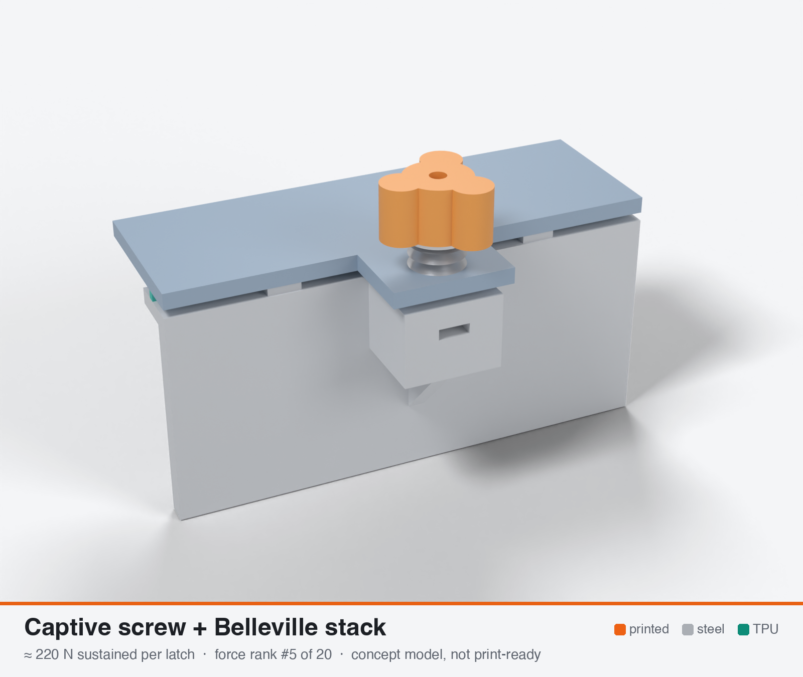
Captive stainless screw clamp with spring or Belleville stack and metal insert
Model note: The 3D model and parts list use an M3 screw into an M3 square nut pushed into a side slot in the boss, where the research used an M4 screw into a heat-set insert. Freeing the lid takes about 6½ turns of the knob; the first 5 unload the springs. In CNC Kitchen's PETG pull-out test a nut in a side slot held 86 kg against 119 kg for a heat-set insert, so leave at least 4 mm of plastic above the nut.
- Force rank
- 5 of 20
- Rank for outdoor sealing
- 3
- Latches for the reference lid
- 7–13
- Build
- Printed + steel hardware
- Hand force to close
- ≈ 22 N
- Adjustable preload
- yes
- Positive compression stop
- no
- Force basis
- calculated
- Review verdict
- corrected
- Confidence
- low
Verdict: Same boss limit as the baseline, slightly lower because a spring holds the load continuously. Best retention of the screw types (calculated about 85-95 % held after hot set, not validated) and removes most of the cold overload. Needs a die spring or Belleville stack, not a small coil.
Why it ranks #3 for sealing: About 220 N (range 110-380) on the simplest printed geometry (boss, insert, washer). The spring stack gives the best calculated retention (about 83-96 % after hot set, unvalidated) and avoids the +100 % cold overload of a rigid screw. Add a printed or steel-sleeve hard stop. Needs a die spring or Belleville stack, since a coil spring light enough to help is impractical. About 11 mm thread depth; usability 4.
On this page
Parts
Per latch: 1 part to print, 6 items to buy, 3 features printed into the box or lid and the TPU 85A seal. Parts marked † are not drawn in the 3D model. In the 3D gallery you can click a part to see where it sits. The last column links the print file, or an example of the part in a shop (see the shopping list).
| Part | Qty | Type | What to use | File or shop |
|---|---|---|---|---|
| Knob | 1 | ASA, flat; the screw head slides into the side slot | knob.stl | |
| Screw | 1 | Buy | M3 × 20 A2/A4 socket screw (DIN 912); its knurled head is pressed and glued into the knob | Grobotronics |
| Square nut | 1 | Buy | M3 square nut (DIN 562), pushed into the side slot in the boss | Grobotronics |
| Disc springs | 5 | Buy | Stainless disc springs for M3 (DIN 2093, 8 × 3.2 mm); together ¼–½ as stiff as the seal | RVS Edelstahl |
| Thrust washer | 1 | Buy | M3 stainless washer at least as wide as the springs | Inox Store |
| Spacer sleeve | 1 | Buy | Brass M3 spacer, 6 mm across, 5 mm long, sanded to 4.6 mm; sits in the lid hole and stops the springs | Grobotronics |
| Retainer † | 1 | Buy | 3 × 1 mm O-ring from the kit, rolled onto the screw just below the spacer sleeve, so the screw stays in the lid when it's open; it tucks into a pocket in the boss | Grobotronics |
| Screw boss | 1 | Printed with the box | Nut slot 5.7 × 2.0 mm opening on the outside, with 4 mm of plastic above the nut; a 4.4 mm pocket on top for the retainer O-ring | box-coupon.stl |
| Lid tab with hole | 1 | Printed with the lid | 6.4 mm hole for the spacer sleeve | lid-coupon.stl |
| Hard stops | 2 | Printed with the box | Pads on the rim either side of the latch, 1.6 mm tall: 0.8 mm below the free seal | box-coupon.stl |
| Seal strip | 1 | Seal (TPU 85A) | TPU 85A, 1.5 × 3.4 mm, in a 1.8 × 1.0 mm groove in the rim; the latch squeezes it 0.8 mm | seal-strip.stl |
Print files
Download all print files for this latch (ZIP, 50 kB)
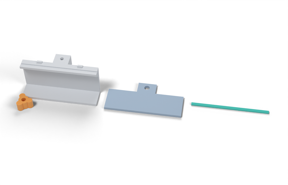
Print in ASA (TPU 85A for the seal), 0.2 mm layers, at least 4 walls; settings and the clearances used are in print/README.md. The parts are already turned the right way up for printing. The box and lid coupons are short test sections with this latch's box-side and lid-side features, so you can try the latch before building it into your own enclosure.
| File | Material | Qty | Size (mm) | How to print |
|---|---|---|---|---|
| knob.stl | ASA | 1 | 17.1 × 18.6 × 10 | Flat, no supports. Press the head of an M3 × 20 socket screw (DIN 912) into the 5.4 mm pocket with a drop of epoxy; the knurled head grips. |
| box-coupon.stl | ASA | 1 | 90 × 39 × 41.6 | Upright, no supports. A section of box wall with this latch's box-side features: seal groove, hard stops. Copy these features into your own box. |
| lid-coupon.stl | ASA | 1 | 90 × 45 × 3 | Flat, top up. A section of lid with this latch's lid-side features. Copy them into your own lid. |
| seal-strip.stl | TPU 85A | 1 | 90 × 3.4 × 1.5 | TPU 85A, 100 % infill, lying on its side. Press it into the rim groove: it stands 2.4 mm proud and the latch squeezes it 0.8 mm, until the lid lands on the hard stops. |
All printed parts in their assembled positions, for CAD: captive-screw-spring-stack.step.
How to assemble
This follows the print files and the parts list above. They are first prototypes, so do one test assembly, on the box and lid coupons, before printing a full set.
Tools: a 2.5 mm hex key, a 5 mm rod or bolt to press with, fine sandpaper on a flat surface, epoxy, calipers and a feeler gauge.
1. Print and prepare
- Print
knob.stlin ASA, flat, as it comes. - Print the box with the screw boss and the two hard stops beside it, and the lid with its tab and 6.4 mm hole, or the box and lid coupons to try it first. Print the boss with 100 % infill.
- Sand the brass spacer down to 4.6 mm long, square on the sandpaper. That's the lid tab (3 mm) plus the gap under the lid when it sits on the stops (1.6 mm). The spacer is the stop for the screw, so measure it with calipers.
- Drop the M3 × 20 screw into the knob from the top and press its head down into the 5.4 mm pocket with the rod, with a drop of epoxy on the head. Let it cure; the knob now turns the screw.
- Check the lid on the bare box: it should rest on the TPU rib with about a 0.8 mm gap above the hard stops. If it already touches the stops, the rib is too low and won't seal.
2. The nut
- Push the M3 square nut into the slot on the outer face of the boss until it lines up with the screw hole; look down the hole to check. The slot opens on the outside, so the screw hole doesn't reach the inside of the box.
3. The stack on the lid
- Push the brass spacer into the lid tab's hole from above, flush with the top of the tab.
- On the screw, under the knob: the thrust washer, then 5 disc springs alternating rim to rim and hole to hole (side view:
> < > < >). - Push the screw down through the spacer.
- Roll the 3 × 1 mm O-ring onto the screw thread just below the spacer. It keeps the screw, springs and knob in the lid when the lid is off. When the lid closes, it tucks into the small pocket on top of the boss.
4. Set the clamp force
Before fitting the springs, measure the 5-spring stack with calipers twice: free, and pressed flat in the calipers' jaws. Your target is the flat height plus a quarter of the difference, about three-quarters of the way to flat.
- Put the lid on the box and turn the knob until the screw catches the nut and the springs just start to tighten. That's zero.
- Turn about 1½ more turns (0.8 mm on M3): the lid squeezes the seal and lands on the hard stops.
- Keep turning until the spring stack is at your target height, about 2 more turns for 8 × 3.2 mm springs. The spacer stops the screw before the springs go flat; if the knob suddenly gets hard, you've reached it, so back off half a turn.
- Check with the latch closed:
- The lid sits on the hard stops: a 0.05 mm feeler gauge won't go in.
- The spring stack is at the target height.
- To open, unscrew the knob until the screw leaves the nut, about 6 turns from closed. Count them once and paint a mark on the knob, so you close it to the same place every time.
5. Final checks
- Open and close it a few times: the screw should find the nut without forcing, and stay in the lid when the lid is off.
- Fit every latch the same way; the reference lid needs 7–13. Tighten them in a cross pattern, opposite sides in turn.
- After the first hot week, check the spring stack height again and turn the knob down to the target if it has grown.
How it works
A captive A4 stainless M4 thumbscrew pulls the lid into a heat-set insert through a stiff spring or disc-spring stack under the head. The spring is about 2-4x softer than the gasket, so the gasket squeeze is set by spring force instead of fixed travel. A few hundredths of a millimetre of gasket set or plastic creep then changes the preload very little. The load path is steel except for the boss, the washer seat and the lid flange.
Mechanical advantage
Screw thread, M4 pitch 0.7 mm. Ideal MA = 2pir/p = 112 at a 12.5 mm knob radius. With K ~0.2 the real hand-to-preload ratio is ~16:1 (22 N at 12.5 mm gives ~0.28 N*m, ~350 N). Friction under a rotating spring end adds torque, so put a thrust washer between spring and knob. The stack converts tight position tolerance into force tolerance: stiffness ratio ks/kg = 1/4 gives 4x the screw travel for the same force.
What limits the force
The same printed boss, insert and washer seat as baseline-screws (~350 N typical). The spring does not raise the force limit. It keeps the force from decaying and from rising in the cold. Practical limit: a spring soft enough to help (ks ~ kg/4 = ~150 N/mm for a 100 mm pitch and 3 N/mm line load) is a heavy die spring or Belleville stack, not a small coil. Coil springs work only for light loads of about 150 N or less.
Analyst's calculation
Analyst's sustained estimate: 250–500 N, typical 350 N; peak 1200 N.
[Web search budget was exhausted this run; no new targeted searches. Boss and insert limits come from the CNC Kitchen tests I re-fetched. The spring model is my own calculation.]
- Boss limits are the same as baseline-screws. M4 insert and washer seat: 250 / 350 / 500 N sustained. Peak ~1.2 kN, taken from the measured M3 PETG insert (1167 N) because I found no M4 printed-host test. A vendor insert paper cites 2.7 kN for M4 but is low confidence.
- Gasket stiffness per latch, design rib: 3 N/mm x 100 mm pitch = 300 N at 20 % of 2.4 mm = 0.48 mm, which gives kg = 625 N/mm secant (about 800 N/mm at 3.9 N/mm).
- Spring rate: ks = kg/4 = 156 N/mm. At 300 N the spring deflects 1.9 mm. Total screw travel = 0.48 + 1.9 = 2.4 mm, about 3.4 turns of M4. Compromise ks = kg/2 = 312 N/mm needs 0.96 mm of spring deflection.
- Spring-type check. Coil spring rate k = Gd^4/(8D^3*N), G ~69 GPa for 302 stainless. For d=1.6 mm, D=9 mm, 1.5 active coils: ~52 N/mm, which suits 50 mm pitch and 2 N/mm (~100 N). For 156 N/mm with d=2 mm and D=10 mm I get less than 1 active coil, which is impractical. So use a die spring, a wave spring or a Belleville stack. Series discs add travel and parallel discs add force. Check against the spring maker's table; I did not source disc spring catalog values.
- Preload loss from gasket set: loss = set x ks/(kg+ks). With ks = kg/4 this is 0.2 x set. With ks = kg/2 it is 0.33 x set. Set of 19 % (23 C Texin) gives 3.8 % / 6.3 %. Set of 35-52 % (70 C Elastollan / Ultrafuse) gives 7-10 % / 12-17 %, against ~33-48 % for the rigid joint (baseline).
- Plastic creep of the member stack, 0.04 mm assumed: with the spring, dF = 125 N/mm x 0.04 mm = 5 N (1.7 %). With a rigid joint it is ~580 N/mm x 0.04 mm = 23 N (8 %).
- Cold: series stiffness rigid joint 580 -> 1173 N/mm (x2.0). Spring chain 125 -> 140 N/mm (x1.12) when the gasket stiffens 2.2x at -30 C. The stack removes most of the cold overload.
- Torque: T = 0.2 x 350 N x 4 mm = 0.28 N*m, ~22 N at a 12.5 mm knob.
- Spring materials: 302/304 stainless is rated to ~288-316 C and is 25-30 % weaker than music wire, which rusts and is limited to ~121 C (Lee Spring, re-fetched). 17-7PH or 316 are alternatives.
- Caveat: a vendor says Belleville washers cut preload loss to under 1 % in steel joints, but that is not validated for plastics, and disc stacks help less in thermally cycled creeping joints. Test on the real boss. I could not re-read the Solon PDF.
Adversarial review
Recomputed the spring maths. Gasket kg = 3 N/mm x 100 mm / 0.48 mm = 625 N/mm, checked. Loss = set x ks/(kg+ks): ks = kg/4 gives 0.2 x set, ks = kg/2 gives 0.33 x set, checked. Cold factor for the stack, 125 to 140 N/mm, is arithmetically right (about +12 %), but it applies the flexural-modulus ratio 59.0/26.9 = 2.2 (verified in Texin) to a compressive stiffness, which is only an approximation, and -30 C is below the -20 C reference. Screw travel (0.48 + 1.9 mm) x 1.3 is about 3.1-3.5 mm and engagement of 2d is about 8 mm, so the boss needs 11 mm or more of thread depth, which the guidelines do not state. Torque 0.28 N*m at K=0.2 is right, and friction under a rotating spring end adds to it. Lee Spring page confirmed: music wire 121 C, rusts when wet, 302/304 stainless 275-300 ksi against 400+ ksi (25-30 % weaker), stainless rated 288-316 C. Boss limits were verified with the same CNC Kitchen pages as baseline-screws. The reason for the lower force, in one line: a spring-loaded joint cannot relax away its overload the way a rigid joint can, so the boss carries the full load continuously. Best use: a stainless Belleville stack or die spring under a washer, with a printed hard stop and a re-torque on the first hot day.
Issues raised:
- Sustained was set equal to the rigid screw (350 N). That is wrong in the direction that matters. The spring makes the boss force-controlled: it holds about the full preload at 60-70 C for months instead of relaxing, so the insert and boss creep-rupture margin is lower than for the rigid screw, not equal. Same boss limits as baseline-screws, minus a small allowance for constant load: typical 220 N.
- The spring helps the seal, not the force ceiling. The preload-retention figures (83-96 % retained) are own calculation only. They ignore spring relaxation at 70 C, stack friction and hysteresis (the analyst's own 10-30 % estimate), TPU stress relaxation, and the 80 % hot set in the Texin sheet. With ks = kg/4 and 80 % set the loss is 16 %, with ks = kg/2 it is 27 %. Seal 9 is not supportable on unvalidated numbers, so 8.
- Hardware reality: ks about 150 N/mm for 300 N at ~2 mm deflection is a die spring or a Belleville stack of 8-10 discs in series. Coil-spring check: Gd^4/(8D^3*N) for d=2, D=10 mm gives N = 0.88 active coils for 156 N/mm, so the analyst's 'impractical' is right. Shear stress at 300 N in a d=2/D=10 coil is about 1.2 GPa corrected, so it also overstresses the wire. Stainless disc stacks tilt, stick and bind with dirt or ice outdoors, and the durability score falls to 7.
- Usability 5 is generous: about 5 turns of a small captive thumbscrew to 0.28 N*m (22 N at a 25 mm knob), a retainer, and no feel for the end of travel. Set to 4.
- Peak 1200 N is above the baseline and is taken from an M3 PETG insert at 23 C with no M4 data. Cap it at 900 N like baseline-screws.
- The Solon 'Belleville cuts preload loss below 1 %' claim is unreadable (the PDF has no extractable text) and applies to steel joints. SPIROL says only that plastics lose clamp load and metal inserts do not. ASME PVP2008 on sciencegate returned 403. None of these supports a number for a plastic boss.
Preload retention outdoors
Good. Calculated ~90-96 % retained with ks = kg/4 and ~83-94 % with ks = kg/2 after 70 C compression set (35-52 %), against 52-67 % for a rigid joint. The cold force rise is ~12 % instead of ~100 %. Not included: TPU stress relaxation, spring relaxation at 70 C, and stack friction hysteresis (all unmeasured). No printed-host test of this arrangement was found.
Materials
ASA for the boss and lid flange. UV-stabilised PC probably raises the sustained limits ~1.3-1.5x (own judgement). Avoid PETG and PETG-CF at 60-70 C, and avoid PA6-CF outdoors. Use A4 stainless for the screw and 302/316/17-7PH for the spring or discs.
Hardware notes from the research
Flagged: not printed. A4 stainless M4 thumbscrew or screw with knob, brass heat-set insert, stainless die/wave spring or 17-7PH/316 Belleville stack, hardened stainless thrust washer, retaining clip or captive O-ring, optional hardened spacer sleeve.
Design guidelines
- Size the spring to the gasket. Target ks = kg/4 to kg/2, where kg = F/delta of the design rib per latch (e.g. 625 N/mm for 3 N/mm at 100 mm pitch and 0.48 mm squeeze). Use coil springs only for loads of about 150 N or less. Above that use a die spring, wave spring or Belleville stack.
- Screw travel must cover gasket squeeze plus spring deflection plus ~30 % margin: ~3.5 mm for a 300 N latch. Use a thread engagement of at least 2 x d.
- A hardened spacer sleeve under the head sets the maximum spring compression at 1.3-1.5x the nominal load, so over-tightening cannot crush the gasket or the boss.
- Seat the spring on a stainless washer with OD at least equal to the spring OD (9-12 mm). Never seat it on bare printed plastic, which creeps under the spring seat.
- Make the screw captive with an E-clip, a retainer ring or an O-ring in the lid hole. A dropped thumbscrew outdoors is a failure.
- Boss, insert and hole sizes as baseline-screws: boss OD >= 14 mm for M4, 100 % infill, hole axis along Z, root fillet >= 2 mm, ribs 1.6-2 mm.
- Add a printed land stop at 0.75-0.8x the free bead height beside each latch. The spring defines the force and the stop caps over-tightening.
- Put a cap over the spring pocket, or a drain hole, so dirt and ice do not bind the stack. Do not use music wire outdoors.
- Pitch is set by rim bending (~28 mm on a flat 3 mm edge, ~110 mm with a 20 mm skirt). Stiffen the rim before adding screws.
Failure modes
- Insert pull-out or boss delamination under sustained hot load. This is the same limit as baseline-screws.
- The spring goes solid, so the joint becomes rigid and loses its benefit. This happens when the user over-tightens or the spring is sized too small.
- Spring or stack friction and hysteresis change the actual preload by 10-30 % (own estimate).
- Music-wire springs rust. Stainless springs relax slightly at 70 C.
- Dirt or ice in the spring pocket binds the stack.
- The captive retainer fails and the screw is lost.
- The disc stack tilts and sticks on the screw.
- The lid screw hole is a water ingress path.
- The boss root cracks in the cold at sharp internal corners.
Evidence gathered in the sweep
SUSTAINED (own est.): 300-500 N, same printed boss and washer seat limit as baseline-screws, but retains most of the preload. PEAK ~1.2 kN. PRELOAD RETENTION (own calc): loss fraction = set x ks/(kg+ks); with ks = kg/4 loss is 0.2 x set = 7-10 % for 35-52 % TPU set, against 35-52 % for a rigid joint https://sushengpolymer.com/media/pdf/yKRdOr_Elastollan-C85A55.pdf . Plastic joints lose clamp load as thickness is lost to creep; metal inserts do not creep https://uk.spirol.com/assets/files/ins-wp-how-to-maintain-joint-integrity-when-converting-from-metal-to-plastic-us.pdf . A vendor white paper claims Belleville washers cut loss below 1 % in steel joints (vendor claim, not validated for plastic) https://www.solonmfg.com/documents/Combatting Embedment Relaxation in Bolted Joints -February 2025 Final Version.pdf ; ASME PVP2008 says springs or longer bolts reduce load loss in flange joints https://www.sciencegate.app/document/10.1115/pvp2008-61005 . Forum advice: smaller fastener plus hardened spacer adds compliance https://eng-tips.com/threads/calculation-of-the-stiffness-of-a-plastic-member-in-a-bolted-joint.502550/latest . Gasket stiffness basis: 3x3 mm bead at 15 % is ~2.4 kN/mm per 117 mm latch share. No printed-host test. CONFIDENCE: medium-low.
Sources
- CNC Kitchen: helicoils, threaded inserts and embedded nuts (PETG M3) — Verified by fetch. Boss and insert limits used for the force ceiling.
- Lee Spring: music wire vs stainless steel — Verified by fetch: music wire ~121 C, rusts when wet, strength above 400 ksi. 302/304 stainless up to ~288-316 C, 275-300 ksi.
- filamentspecs: creep resistance of 3D printed parts — Verified by fetch. PETG joints lost ~11.5 % preload in 7 days against ~3 % for PLA.
- Elastollan C85A55 datasheet (TPU 85A compression set) — From brief, not re-fetched. 25 % set at 23 C and 35 % at 70 C. Used for the loss calc.
- Texin 985 datasheet — From brief, not re-fetched. Set 16-19 % at 23 C and 40-80 % at 70 C. Modulus x2.2 at -30 C.
- SPIROL: maintaining joint integrity when converting from metal to plastic — From brief, not re-fetched. Plastic joints lose clamp load as thickness creeps and metal inserts do not.
- Solon: combatting embedment relaxation in bolted joints — Vendor claim for steel joints. The fetch returned raw PDF only, so I could not re-read it. Not validated for plastics.
- ASME PVP2008: Belleville washers to reduce load loss in flange joints — From brief, not re-fetched. Metal flange context.
Sources the reviewer flagged (dead, blocked or misdescribed):
- https://www.solonmfg.com/documents/Combatting Embedment Relaxation in Bolted Joints -February 2025 Final Version.pdf : text not readable; the under-1 % figure cannot be verified, and steel-joint context in any case
- https://www.sciencegate.app/document/10.1115/pvp2008-61005 : HTTP 403, unverified
- https://uk.spirol.com/assets/files/ins-wp-how-to-maintain-joint-integrity-when-converting-from-metal-to-plastic-us.pdf : qualitative only (plastic creep and relaxation, metal inserts do not creep); no quantified preload loss, no spring data
- https://filamentspecs.com/creep-resistance-3d-printed-parts/ : secondary figure from an MDPI aging study; conditions not stated