No. 13 of 20 · Round lids only
Bayonet / twist lock
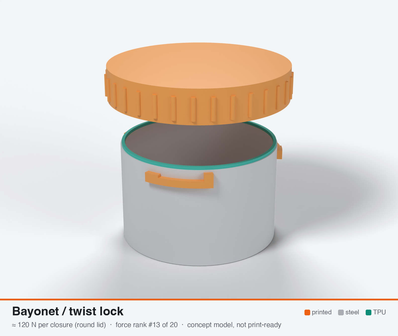
Bayonet / twist-lock lid with ramps
Round lids only. The force below is for one whole closure, not one latch on a rectangular lid.
- Force rank
- 13 of 20
- Build
- Fully printed
- Hand force to close
- ≈ 75 N
- Adjustable preload
- no
- Positive compression stop
- yes
- Force basis
- calculated
- Review verdict
- confirmed
- Confidence
- low
Verdict: Round lids only. Torque and TPU drag give 92-183 N at 2-4 Nm, and the lug roots across layers give 120-180 N. Fixed ramp height, no re-tightening, 30-58 % hot loss. About 0.7 N/mm, so it suits only small lids.
On this page
Parts
Per closure: 2 parts to print, 2 items to buy and the TPU 85A seal. Parts marked † are not drawn in the 3D model. In the 3D gallery you can click a part to see where it sits. The last column links the print file, or an example of the part in a shop (see the shopping list).
| Part | Qty | Type | What to use | File or shop |
|---|---|---|---|---|
| Container with lugs | 1 | ASA, upright; 3 lugs, each with a stop, a flat dwell and a ramp that draws the lid down 1.2 mm | can.stl | |
| Bayonet lid | 1 | ASA, upside down; 3 inward lugs | lid.stl | |
| Seal ring | 1 | Seal (TPU 85A) | TPU 85A, 1.4 × 3.2 mm, on the rim outside the lip; 0.8 mm squeeze | seal-ring.stl |
| Detent (optional) † | 1 | Buy | M4 A4 spring plunger or ball detent | Leschhorn |
| Slip washer (optional) † | 1 | Buy | PTFE or PE, under the seal ring | S-Polytec |
Print files
Download all print files for this closure (ZIP, 0.2 MB)
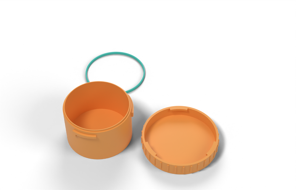
Print in ASA (TPU 85A for the seal), 0.2 mm layers, at least 4 walls; settings and the clearances used are in print/README.md. The parts are already turned the right way up for printing.
| File | Material | Qty | Size (mm) | How to print |
|---|---|---|---|---|
| can.stl | ASA | 1 | 82.6 × 82.6 × 52.4 | Upright, no supports (the lugs are a 2.6 mm overhang). Drop the lid's lugs into the gaps and turn it 44 degrees until it hits the stops. |
| lid.stl | ASA | 1 | 93.4 × 93.4 × 17 | Upside down, no supports; the inward lugs are a short 2.7 mm overhang. |
| seal-ring.stl | TPU 85A | 1 | 79.7 × 79.7 × 3.2 | TPU 85A, 100 % infill. Sits on the rim outside the lip; the lid squeezes it 0.8 mm. |
All printed parts in their assembled positions, for CAD: bayonet-twist-lock.step.
How it works
Radial lugs on the lid slide under helical ramps (retaining ledges) on the body; rotating the lid 30-45 degrees climbs the ramps and pulls the lid axially onto the gasket, ending in a flat dwell with a detent. A shallow ramp (3-8 deg) is self-locking against the gasket spring-back (tan 5 deg = 0.09 versus friction 0.15-0.25), but vibration can still rotate it back, so a detent is needed. The whole lid is one closure with no latch count, but force is limited by hand torque, TPU ring scrubbing during rotation, and the lug roots, which are loaded across layers when the axis is vertical.
Mechanical advantage
Ramp: F = T / (r tan(alpha + phi)). For r = 27 mm and a 5 deg ramp the frictionless T/F is r tan(alpha) = 2.4 mm (ideal ratio about 15:1 at a 35 mm wing lever); with ramp friction mu 0.25 it is 9.3 mm (mu 0.15: 6.5 mm); adding TPU drag (mu_c 0.5 at r_c 25 mm = 12.5 mm) gives about 22 mm, i.e. an effective ratio of only about 1.6:1 at the wing. Steeper ramps give less force per torque. (all own calc)
What limits the force
Hand torque divided by ramp friction plus TPU-ring drag (about 95-180 N typical at 2-4 Nm), and the lug roots in bending across layers (about 180-270 N sustained for 16 x 3 x 5 mm lugs, with only two of three lugs bearing in practice).
Analyst's calculation
Analyst's sustained estimate: 50–200 N, typical 120 N; peak 700 N.
ASSUMED PART (own): 56 mm OD lid, 3 lugs at 120 deg, each 16 mm arc x 3 mm radial x 5 mm thick; ramp contact radius r = 27 mm, ramp 5 deg, about 40 deg of rotation including a 4 mm dwell with detent; ASA; lid printed sealing-face down, axis vertical.
- Torque to axial force: F = T / [r tan(alpha + phi) + mu_c r_c] (ramp formula as in the lead's evidence, with TPU drag added by me). Friction 0.25 plastic/plastic, 0.15 plastic/steel (https://elesa.com/en/elesab2bstoreca/Clamping-handles--Cam-levers--GN9272-A--d1). r tan(alpha+phi) = 9.3 mm (mu 0.25), 6.5 mm (mu 0.15); frictionless 2.4 mm. TPU drag (mu_c NOT sourced, assumed 0.5; 0.8 worst; 0.1 with a slip washer) at r_c 25 mm adds 12.5 mm (20 mm worst, 2.5 mm best). At 2 / 3 / 4 Nm: ramp-only 215 / 322 / 430 N; typical with TPU drag (T/F 21.8 mm) 92 / 138 / 183 N; best case (mu 0.15 + slip washer) 222 / 333 / 444 N; worst case at 2 Nm about 70 N.
- Lugs (own beam calc). Each lug carries P = F/3 at an arm l = 1.5 mm; the root bending stress acts along the axis, i.e. across layers for a vertical print: sigma = 6 P l / (b h^2) = 6 x 1.5 x P / (16 x 25) = 0.0225 MPa per N. Sustained across-layer allowable about 2 MPa (project brief) gives P = 89 N, F = 267 N for three lugs, about 180 N when tolerances leave only two lugs bearing. Peak: roughly 12 MPa across layers at room temperature (ASA standing hooks reach only 29 percent of lying, https://cnckitchen.com/blog/comparing-pla-petg-amp-asa-feat-prusament) divided by Kt 1.5 gives P = 355 N, F about 1070 N, x 2/3 = about 710 N. Lug shear and bearing (P/(16 x 5) and P/(16 x 3)) stay near 1-2 MPa, well below limits.
- Result: sustained low / typical / high = 50 / 120 / 200 N (2 Nm with heavy drag / 2.6 Nm typical case / lug limit); peak 700 N. On the 170 mm lug circle the typical value is about 0.7 N/mm, far below the 2-4 N/mm window; a lid reaches 2 N/mm only if its circumference is under about 60 mm (diameter about 20 mm). Nothing in the lead's evidence conflicts: no pull-off or torque tests exist for printed bayonets (maker and industrial estimates 50-300 N), so this remains a low-confidence calculation. Further web searches were blocked (search budget exhausted); MakerWorld pages returned HTTP 403.
Adversarial review
I recomputed the ramp formula F = T / (r tan(alpha+phi) + mu_c r_c). The results are 92 / 138 / 183 N at 2 / 3 / 4 Nm for mu 0.25, mu_c 0.5, and 333 N at 3 Nm for the best case (mu 0.15, slip washer). The analyst's typical of 120 N is confirmed. The lug cantilever (16 x 3 x 5 mm, arm 1.5 mm) gives 0.0225 MPa per N, so 2 MPa gives 267 N (three lugs) or 178 N with Kt 1.5. The brief's across-layer allowable of 2 MPa is the key assumption and is unmeasured for ASA at 60-70 C. The peak uses 12.7 MPa (0.29 x 43.8 MPa Polymaker XY), which agrees with the CNC Kitchen 29 percent standing-hook ratio. Sources: Wikipedia Bayonet mount fetched and consistent (L-slot, spring-loaded detent, failure by peg or sleeve breakage, spring failure or vibration; it says bayonets resist vibration better than screw joints). Elesa friction confirmed. CNC Kitchen hook ratio confirmed. Ultrafuse set 26/52 percent confirmed. Hackaday.io log confirmed as qualitative only (PLA split along layers, no numbers). Both MakerWorld and stlfinder pages were HTTP 403 and could not be checked. Neither drives a force number. My search budget was exhausted, so I found no published pull-off or torque test for printed bayonets. The result is a calculation only, and I mark the confidence low. Verdict is confirmed because the typical lands within 5 percent and the sources that drive the force numbers check out; peak, high, scores trimmed.
Issues raised:
- Ramp arithmetic confirmed: r tan(alpha+phi) = 9.3 mm (mu 0.25), 6.5 mm (mu 0.15); plus TPU drag 12.5 mm gives 92 / 138 / 183 N at 2 / 3 / 4 Nm. The typical 120 N at about 2.6 Nm reproduces. As with the cap, the TPU-on-ASA mu_c of 0.5 is unsourced. mu_c 0.8 gives 68 N at 2 Nm, and mu_ramp 0.35 gives about 100 N at 2.5 Nm.
- The lug limit was computed without a stress concentration. The root stress is 0.0225 MPa per N (recomputed), so 2 MPa across layers gives 267 N for three lugs. With Kt 1.5 it is 178 N for three lugs and 119 N when tolerances leave two lugs bearing. So the lug ceiling and the hand-torque result nearly coincide at 120-180 N, and the high case is trimmed from 200 to 180 N.
- Peak of 700 N relied on Kt 1.5. With a more realistic printed-fillet Kt of 2 it is about 565 N (Kt 1.5 gives 750 N). Lowered to 600 N. Peak is not hand-deliverable: 600 N at 22 mm T/F is about 13 Nm.
- The mating ledge on the body is an equal cantilever loaded across layers when the axis is vertical, and was not checked. Typically it has a longer arc and is stronger than the lugs, but it is a second weak point.
- Cold, fixed stroke: the 85A modulus at -20 C is about 2x, so the dwell force would be 180-240 N (above the lug sustained limit), and the lid may not reach the dwell at 3 Nm. Hot: the 52 percent set at 70 C cuts force 30-58 percent and cannot be re-tightened. The sustained range is therefore wide (about 60-240 N over the year).
- At about 0.7 N/mm typical on a 170 mm lug circle (confirmed), it is far below the 1.7 N/mm Garlock-equivalent for a 1.2 mm rib and below the 2-4 N/mm window. Seal suitability is lowered from 4 to 3. Practical only for small round lids or thin foam/lip seals.
- Usability is lowered from 8 to 7. It is a quick 40 deg turn, but it needs a wing and 2.6 Nm (about 33 N per finger on 40 mm arms), a fussy three-lug alignment, and extra effort when cold. The conventional bayonet has a spring detent and no force data exists for printed lugs.
Preload retention outdoors
Poor. The ramp is a rigid fixed-travel element, so about 30-58 percent of force is lost when 85A TPU takes a set at 70 C (Ultrafuse 85A set 52 percent at 70 C, https://www.dream3d.co.uk/wp-content/uploads/2022/12/Ultrafuse_TPU_85A_TDS_EN_v2.5.pdf), and ASA ramps and lugs creep further. The preload is fixed by the ramp dwell height and cannot be re-tightened without shims; a steel wave spring under the TPU or a flexible ramp would be needed.
Materials
ASA for the lid and body ledges. PC (UV-stabilised) raises lug and creep margin about 1.3-1.5x (own judgement) but not the hand-torque limit. PETG is marginal at 60-70 C. PA6-CF not recommended outdoors (moisture). A metal ramp insert or stainless detent pin helps wear.
Hardware notes from the research
None required. Optional: A4 stainless spring plunger or ball detent (M4) for the dwell, PE/PTFE slip washer under the TPU ring, A4 pins as lugs if the printed lugs are the limit.
Design guidelines
- Use 3 lugs at 120 deg, each at least 16 mm of arc, 3 mm radial, 5-6 mm thick, with R at least 1.5 mm fillets at the root (root bending across layers is the weak spot for a vertical print).
- Ramp 4-6 deg (self-locking) with a 3-5 mm flat dwell plus a 0.3-0.4 mm detent bump and a hard rotation stop; the ramp end height should set the squeeze at about 0.75-0.8 x free rib height.
- Print the body open-end-down on the bed so the ramp bearing faces sit at the bed and need no bridging or support; print the lid sealing-face down.
- Wings or a lever at least 35 mm radius so 2.5-3 Nm needs under 80 N finger force.
- Keep the TPU rib narrow (1.2-1.6 mm) and put it on the non-rotating part; use an ironed land or slip washer on the rotating face to cut drag.
- Apply a second print-quality check on the three ramps: all three must bear equally, so tune with 0.1 mm shims or print the ledges as separate adjustable pads.
- Rated use: small round lids up to about 20-30 mm for a 2-4 N/mm gasket; larger lids need a different latch.
- Include a visual lock-position mark and a finger lead-in chamfer so the lugs enter the entry slots without cocking.
Failure modes
- Lug root delamination across layers; one of three lugs overloaded by tolerances.
- Ramp and dwell creep or wear, so the lid loosens over months in sun.
- Lid unwinds with vibration if no detent or if the detent creeps.
- TPU ring scrubbing and rolling during rotation; an under-extruded sealing face leaks.
- Overhanging ramp sagging or stringing in print, giving uneven squeeze.
- Dirt, ice or sand packed in the slots jams the lugs.
- Force too low (about 0.7 N/mm typical) so the gasket leaks on lids larger than about 20 mm.
Existing designs and commercial references
- MakerWorld heavy-duty two-lug bayonet lid — PETG, printed upside-down, designer reports months outdoors (via lead search text); HTTP 403 to my fetch, no force data
- Customizable Waterproof Pill Box (stlfinder) — About 1/8-turn bayonet; claims 10 cm for 10 min; HTTP 403 to my fetch, so claim not re-verified
Evidence gathered in the sweep
SUSTAINED (own est., whole lid, low confidence): 50-300 N (maker estimate 50-150 N shared over ~3 lugs; industrial estimate 150-300 N); PEAK 300-600 N. RAMP CALC (own): F = T/(r tan(alpha+phi)); T 2 Nm, r 25 mm, ramp 3/5/10 deg, mu 0.2 gives ~314/273/205 N; mu 0.3 gives ~223/201/159 N. EVIDENCE: heavy-duty two-lug MakerWorld bayonet lid in PETG, designer reports months outdoors (search text) https://makerworld.com/models/1924555 ; bayonet pill box closes in about 1/8 turn, claims 10 cm for 10 min, warns under-extruded seal leaks (search text) https://www.stlfinder.com/model/customizable-waterproof-pill-box-FhdEExnI/2424312 ; Wikipedia, which I fetched, confirms the lock relies on pegs, slots and a spring or detent and can fail if pegs break or the spring weakens https://en.wikipedia.org/wiki/Bayonet_mount . No pull-off or torque tests found. CONFIDENCE: low.
Sources
- Wikipedia: Bayonet mount — Principle (pegs, slots, detent or spring) and failure modes; fetched by the lead, not by me
- Elesa GN 927.2 page (friction coefficients) — Fetched: plastic/plastic 0.25, plastic/steel 0.15
- CNC Kitchen: comparing PLA, PETG and ASA (Prusament) — Standing-vs-lying hook figures (ASA 17 vs 57 kg) taken from the project brief, not re-fetched
- Ultrafuse TPU 85A datasheet — Compression set figures from the project brief, not re-checked
- Hackaday.io: printed cap splits along layers under bolt force — Fetched: layer splitting of an as-printed PLA part under bolt force; supports the across-layers lug concern, no numbers
Sources the reviewer flagged (dead, blocked or misdescribed):
- https://makerworld.com/models/1924555 - HTTP 403, 'months outdoors in PETG' claim unverifiable.
- https://www.stlfinder.com/model/customizable-waterproof-pill-box-FhdEExnI/2424312 - HTTP 403, '10 cm for 10 min' claim unverifiable.
- https://hackaday.io/project/12125/log/41900 - live, but PLA with no numbers; it supports only the qualitative across-layers concern.