No. 14 of 20 · Rectangular lids
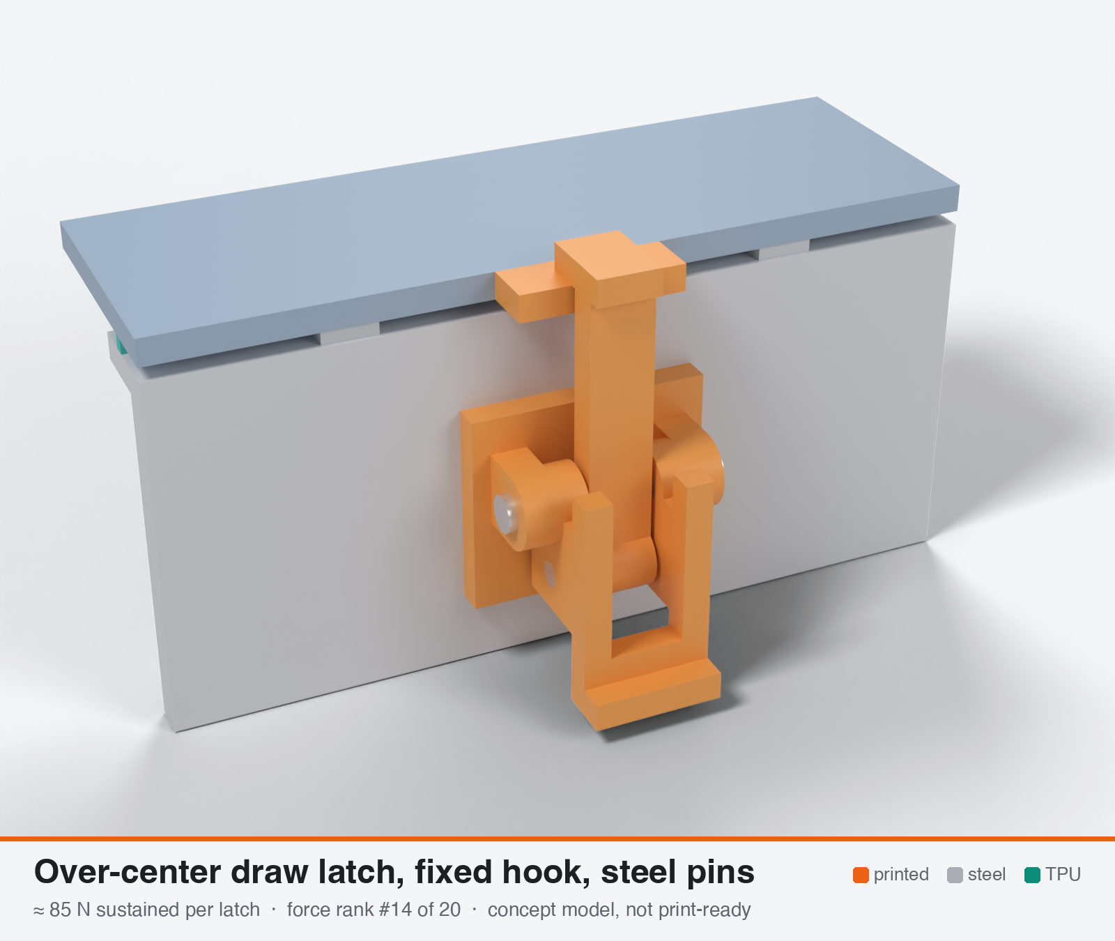
Over-center draw latch, fixed hook, steel pins
Over-center draw latch, printed body, steel pivot pins, fixed hook
- Force rank
- 14 of 20
- Latches for the reference lid
- 17–33
- Build
- Printed + steel hardware
- Hand force to close
- ≈ 7 N
- Adjustable preload
- no
- Positive compression stop
- no
- Force basis
- calculated
- Review verdict
- corrected
- Confidence
- low
Verdict: Cut from 110 N. The printed claw throat is a curved-beam limit of about 40-70 N, with a bent A4 wire hook the only route to 100 N or more. No adjustment, so +/-0.3 mm of tolerance is +/-160 N. After hot set the line load falls to about 1 N/mm or less.
On this page
- Parts
- Print files
- How it works
- Mechanical advantage
- What limits the force
- Analyst's calculation
- Adversarial review
- Calibration adjustments
- Preload retention outdoors
- Materials
- Hardware notes from the research
- Design guidelines
- Failure modes
- Existing designs and commercial references
- Evidence gathered in the sweep
- Sources
Parts
Per latch: 3 parts to print, 4 items to buy, 3 features printed into the box or lid and the TPU 85A seal. Parts marked † are not drawn in the 3D model. In the 3D gallery you can click a part to see where it sits. The last column links the print file, or an example of the part in a shop (see the shopping list).
| Part | Qty | Type | What to use | File or shop |
|---|---|---|---|---|
| Base | 1 | ASA, flat on its back; ears with 4.25 mm bores | base.stl | |
| Lever | 1 | ASA, on its side with supports under the upper cheek; 3.9 mm press holes for the pins | lever.stl | |
| Hook link | 1 | ASA, lying on its side; neck 7.2 × 5.7 mm | hook-link.stl | |
| Base screws † | 2 | Buy | M3 × 10 A2/A4 socket screws (DIN 912) | Grobotronics |
| Square nuts † | 2 | Buy | M3 square nuts (DIN 562), dropped down the channels in the box wall | Grobotronics |
| Pivot pins | 2 | Buy | 4 mm steel pins, 8 mm long, cut from 4 mm shaft; pressed into the lever cheeks, they turn in the base | Grobotronics |
| Link pin | 1 | Buy | 4 mm steel pin, 14 mm long; pressed through both cheeks | Grobotronics |
| Keeper | 1 | Printed with the lid | Ledge on the lid edge, 18 × 6 mm, loaded in compression | lid-coupon.stl |
| Hard stops | 2 | Printed with the box | Pads on the rim either side of the latch, 1.6 mm tall: 0.8 mm below the free seal | box-coupon.stl |
| Nut channels | 2 | Printed with the box | Inside pillar with a 5.7 × 2.0 mm channel per nut, open on the rim outside the seal; blind 3.4 mm screw holes, so no path into the box | box-coupon.stl |
| Seal strip | 1 | Seal (TPU 85A) | TPU 85A, 1.5 × 3.4 mm, in a 1.8 × 1.0 mm groove in the rim; the latch squeezes it 0.8 mm | seal-strip.stl |
Print files
Download all print files for this latch (ZIP, 91 kB)
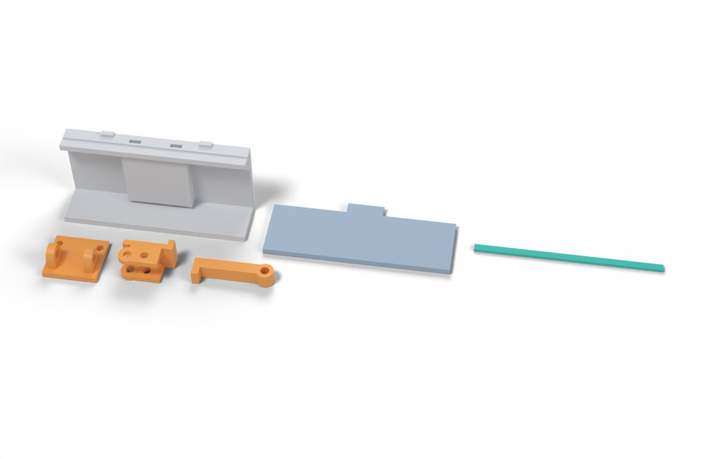
Print in ASA (TPU 85A for the seal), 0.2 mm layers, at least 4 walls; settings and the clearances used are in print/README.md. The parts are already turned the right way up for printing. The box and lid coupons are short test sections with this latch's box-side and lid-side features, so you can try the latch before building it into your own enclosure.
| File | Material | Qty | Size (mm) | How to print |
|---|---|---|---|---|
| base.stl | ASA | 1 | 26 × 24 × 13 | Flat on its back, no supports. 2 × M3 × 10 into the box. The pivot pins turn in these bores. |
| lever.stl | ASA | 1 | 24.5 × 16.5 × 13.5 | On its side (pin axis vertical), supports under the upper cheek. Press the pivot pins and the link pin into the 3.9 mm holes. |
| hook-link.stl | ASA | 1 | 38.3 × 10.8 × 7.2 | Lying on its side, no supports, so the hook bends along the layers. |
| box-coupon.stl | ASA | 1 | 90 × 24 × 41.6 | Upright, no supports. A section of box wall with this latch's box-side features: seal groove, hard stops, and an inside pillar with nut channels. Push an M3 square nut down each of the 2 channels in the rim before fitting the screws. Copy these features into your own box. |
| lid-coupon.stl | ASA | 1 | 90 × 36 × 3 | Flat, top up. A section of lid with this latch's lid-side features. Copy them into your own lid. |
| seal-strip.stl | TPU 85A | 1 | 90 × 3.4 × 1.5 | TPU 85A, 100 % infill, lying on its side. Press it into the rim groove: it stands 2.4 mm proud and the latch squeezes it 0.8 mm, until the lid lands on the hard stops. |
All printed parts in their assembled positions, for CAD: oc-fixed-hook-pinned.step.
How it works
Printed lever, link and base pivot on 3 mm (or M4) stainless pins. The hook is a printed claw or a bent stainless-wire hook with fixed take-up. The lever swings through dead centre (keeper-P1 line) to about 0.5-0.7 mm over-centre and locks without friction. Clamp force is the fixed geometric interference times the series stiffness of hook, frame and gasket, so it scatters with every tolerance and falls as the TPU takes set. Pivot axes along Z, with lever, link and hook lying in the XY plane. A bent wire hook, or a 2 mm TPU pad between hook and mating side (MakerWorld 1054989), adds a little elasticity.
Mechanical advantage
Lever 60 mm, e = 10 mm, engagement stroke 1.5 mm (own calc, includes tolerance padding): geometric MA at the worst point = 60/2.11 = 28:1; about 21:1 after pin friction (3 mm pins, mu 0.25). Static MA at lock (0.6 mm over-centre) about 100:1. There is no adjuster: the hook force is whatever the interference gives.
What limits the force
The printed hook neck (tension plus offset bending) and the 3 mm pin bearing in ASA at 60-70 C. A second weakness is not strength but scatter: with about 530 N/mm of series stiffness, 0.3 mm of tolerance moves the force by 160 N, as large as the allowable.
Analyst's calculation
Analyst's sustained estimate: 110–210 N, typical 155 N; peak 500 N.
DIMENSIONS (my choice): hook neck 12 mm wide x 8 mm thick (lying in XY), load line offset a = 3 mm from the neck centre line, inner fillet R 3 mm; lever plate 8 mm; 3 mm A4 pins (bearing 3 x 8 = 24 mm2); base on a 3.5 mm wall with 2 x M3 (3 x 3.5 x 2 = 21 mm2). ALLOWABLES: net section 3 / 4 / 5.5 MPa; bearing 6 / 8 / 10 MPa (brief working rule). HOOK NECK: sigma = F/(t w) + 6 F a/(t w^2) = F/96 + 18 F/1152 = 0.0260 F. At 3 / 4 / 5.5 MPa: 115 / 154 / 211 N <- governs. PIN BEARING: 24 mm2 -> 144 / 192 / 240 N. WALL BEARING: 21 mm2 -> 126 / 168 / 210 N. Result: sustained about 110 / 155 / 210 N. If the offset grows to 6 mm the neck allowable drops to 70 N, so keep the load line in the neck. PEAK: neck at about 16 MPa nominal (37 MPa XY ultimate over Kt of about 2.3) = 615 N; pin 24 x 27 = 650 N; wall 21 x 25 = 525 N. Report 500 N (400-900 in the brief). Standing orientation: 29 % of lying (CNC Kitchen ASA hook 17 vs 57 kg), so about 150 N peak and about 45 N sustained, which is why orientation is a hard rule. HAND FORCE: (2.11 F geometric + 0.75 F friction) mm = 2.86 F mm; at 155 N and 60 mm that is about 7 N. FIT TO LOAD: 8 latches x 155 N = 1.24 kN = 1.8 N/mm (700 mm path) as set; after hot set (-33 %) about 830 N = 1.2 N/mm, below the 2-4 N/mm window. SCATTER: k_series = 1500 x 830/2330 = 534 N/mm (k_l = 1500 N/mm assumed); +/-0.3 mm of take-up gives +/-160 N, which is +/-100 % of the nominal 155 N. BENCHMARKS: Southco 37 lever-assist (GF nylon, stainless pins) 350 N clamping force, 475-520 N top variant (listings disagree; carried from the brief, datasheet copy could not be parsed); MakerWorld Draw Latch survived about 187 N but stretched out of position; M3 toggle latch claims above 10 kg. EVIDENCE STATUS: no printed sustained test found; the web-search budget was exhausted in this run. Confidence low-medium.
Adversarial review
Recomputed: neck coefficient 0.0260 (matches); pin 3x8 bearing 144/192/240; wall 2xM3 21 mm2 126/168/210 (match); series stiffness 1500x830/2330 = 534 N/mm (match); set loss 0.52 x 1500/2330 = 33 % (match), cold +54 % (match). Hand force with the correct stroke at 155 N is about 4.3 N (analyst 7 N; conservative). The only substantive change is the missing Kt/curved-beam effect at the claw, which drops the governing limit from 154 N to about 102 N; I report 110 N typical (70-150), which includes a small credit for the wire-hook variant. Peak is trimmed from 500 to 450 N for consistency with the 20-25 MPa bearing peak used in the other mechanisms. The CNC Kitchen hook ratio (ASA 57 kg flat vs 17 kg standing, 29 %) and the PC Blend figures (74-77 kg flat, 22-35 kg standing) are verified. Scores: seal 4 to 3 (see end-of-life calc), durability 7 to 6 (no outdoor data), usability 8 to 7 (no adjustment, a tolerance-sensitive keeper).
Issues raised:
- The hook-neck calculation is a straight-beam formula with no stress concentration: sigma = F/96 + 18F/1152 = 0.0260 F (arithmetic correct). A claw hook is a curved beam with h/ri of about 4-5 at the throat, so the inner-fibre factor is near 2 and the fillet Kt adds to that. With an effective factor of 1.5 the neck allows 77/102/141 N, not 115/154/211. The printed claw governs at about 100 N.
- A bent A4 wire hook, which the analyst suggests, removes the neck limit. Capacity is then set by 3 mm pin bearing (144/192/240 N) and wall bearing (126/168/210 N), about 140-150 N after derating. This is a different design from the printed claw that was computed, so the typical should follow the printed claw.
- The Southco 37 benchmark is misfiled. The datasheet (chipdip copy, which I decoded) describes a flexible EPDM-rubber over-center latch with glass-filled nylon and stainless pins, nominal clamp force 110/190/350 N and 475 N for the top variant, rated -40 to 80 C. The rubber body is a series spring, so this supports the spring-backed class, not a rigid fixed hook. The '475-520 N' range is also off: 475 N is the top variant and 520 N appears nowhere.
- Delivered end-of-life force is the real issue. The as-set force decays to about 0.63 x as-set minus creep, so about 55-60 %. At 110 N as-set, 8 latches deliver about 520 N at end of life on a 700 mm path, which is 0.75 N/mm. That is far below the 2-4 N/mm design window. Seal score 4 to 3.
- Scatter of +/-0.3 mm gives +/-160 N at 534 N/mm. This is as large as the capacity, so one latch can crush the rib while its neighbour leaks. A hard stop only transfers that load into the latch. The stiff series spring or adjuster is not optional.
- The CNC Kitchen PA6/PA12 article does not give separate ASA and PLA re-tightening counts. It says only that PA12 needed one re-tighten, similar to PLA and ASA. The brief's claim is loosely supported.
- The 187 N Draw Latch result (MakerWorld 2266330) could not be fetched, and its material and 'stretched out of position' outcome mean it is a weak anchor.
Calibration adjustments
- sustained_N.typical: 110 (reviewer; range 70-150) → 85 (range 50-130). The analyst's neck check puts the load line 3 mm off the neck centre line on a straight beam. A real claw throat (inner radius about 2 mm, load line through the centre of curvature) gives about 0.10 MPa/N by the Winkler method used for the cam-hook and bail reviews, which is about 40-70 N at 4-7 MPa. The reviewer's 110 N credits an unmodelled bent-wire hook; set to a blend of the printed claw and the wire variant.
Preload retention outdoors
Poor. k_l about 1500 N/mm vs gasket 830 N/mm per 100 mm pitch: set loss = s x k_l/(k_l + k_g) = 0.64 s, so 33 % at 70 C with Ultrafuse set 52 %, 17 % at 23 C (26 % set); Texin moulded set of 40-80 % at 70 C gives 26-51 %. ASA hook and pin creep adds about 0.03 mm x 534 N/mm = 16 N (10 %). Cold: +54 % at -30 C for the same stroke (534 -> 824 N/mm). Expect about 55-65 % of preload after the first hot summer and no way to restore it except by re-making the hook position (shims, slotted keeper). To end up with 110 N at end of life you must assemble at 165 N or more, which is already at the typical sustained limit. Not adjustable.
Materials
ASA default; UV-stabilised PC probably 1.3-1.5x higher sustained (my judgement). PETG and PETG-CF marginal at 60-70 C (HDT 68 C). PA6-CF avoid outdoors. Bent A4 stainless wire hook instead of a printed claw removes the weakest link and adds elasticity.
Hardware notes from the research
Two or three A4 stainless 3 mm pins (or M3/M4 shoulder screws) with e-clips, optional bent 2-2.5 mm A4 wire hook, optional 2 mm TPU support pad, 2 x M3/M4 heat-set inserts or screws with washers for the base, stainless keeper pin.
Design guidelines
- Print lever, link and hook lying flat (pin axes along Z). Never print the hook standing: ASA keeps 29 % of lying strength.
- Hook neck at least 12 x 8 mm, load line within 3 mm of the neck centre line, inner fillet R 3 mm or more; or replace the claw by a bent A4 wire hook.
- 3 mm pins give 24 mm2 of bearing; 4 mm pins with a 9 mm lever give 36 mm2 and about 40 % more load, so use 4 mm if the envelope allows.
- Give the keeper a slotted or stepped position (0.25 mm steps) so tolerance can be trimmed at assembly; add a printed hard stop beside each latch at 0.75-0.8x the free bead height.
- Add a steel series spring or accept that a 2 mm TPU pad carries its own 52 % compression set at 70 C. Do not count the TPU pad as the spring.
- 4-5 perimeters, 100 % infill in lug zones, 0.15-0.2 mm layers, internal fillets R 2 mm or more.
- Wall pad at least 6 mm thick under the base with inserts, otherwise the 3.5 mm wall bearing (about 170 N typical) is the weakest link. Space latches at 100 mm pitch or less, with stiffened rim.
- Mark and check the set point after the first hot week; replace shims or hook if force has fallen.
Failure modes
- Fixed take-up scatter: a tolerance stack that is too tight crushes the rib or breaks the hook neck; too loose leaves the lid leaking.
- Compression set of the 85A bead (up to 52 % at 70 C) loses a third of the preload with no way to re-tension.
- Hook neck cracks from combined tension and offset bending, usually at the inner fillet, faster in cold ASA.
- Pin bore and screw hole creep ovalises the pivots at 60-70 C.
- Pin retention fails (e-clip lost) or the pin works out through vibration.
- Screw tearing out of the housing (designers report this as the usual printed-latch failure); wall count matters more than infill.
Existing designs and commercial references
- MakerWorld Self-Locking Toggle Latch 1054989 — steel/stainless 3 mm pins and a 2 mm TPU pad; no force values (carried from the brief, HTTP 403)
- MakerWorld Draw Latch 2266330 — survived about 42 lb (187 N) without breaking but stretched out of position; lower bound only (carried from the brief, HTTP 403)
- M3 Toggle Latch High Performance (STLFinder) — claims more than 10 kg (about 98 N) (carried from the brief, HTTP 403)
Evidence gathered in the sweep
SUSTAINED (own est., ASA, SF~2): 120-250 N (maker estimate from 3 mm pin bearing ~3x6 mm per wall; industrial estimate 100-300 N; reconciled). PEAK (own est.): 400-900 N. PLASTIC-BODY BENCHMARKS: Southco 37 lever-assist (GF nylon, stainless pins) 350 N clamping force, top variant 475 N (Marek) or 520 N (other listings, sources disagree), -40 to 80 C https://static.chipdip.ru/lib/031/DOC015031575.pdf and https://www.marek.eu/katalog-obrazku/produkt-8066/66871-37-l-en.pdf ; injection-moulded 30 % GF nylon is several times stronger than printed ASA. PRINTED EVIDENCE: MakerWorld Draw Latch survived ~42 lb (~187 N) without breaking but stretched out of position (lower bound, PLA-class, one anecdote) https://makerworld.com/en/models/2266330-draw-latch ; M3 toggle latch claims >10 kg https://www.stlfinder.com/model/m3-toggle-latch-high-performance-wkO8uZca/4063366 ; MakerWorld 1054989 has 3 mm steel and stainless pins and a 2 mm TPU pad, no force values https://makerworld.com/en/models/1054989-self-locking-toggle-latch . HOOK PROXY (CNC Kitchen): ASA hook lying 57 kg vs standing 17 kg; SF 2 gives ~280 N lying and ~83 N standing, for that test geometry only https://cnckitchen.com/blog/comparing-pla-petg-amp-asa-feat-prusament . Designers report failure by screw tearing out of the housing and say wall count matters more than infill. CONFIDENCE: low-medium.
Sources
- CNC Kitchen: comparing PLA, PETG and ASA (hook tests) — fetched: ASA hook lying 57 kg vs standing 17 kg (29 %); PETG 55 vs 25; PLA 73 vs 40
- Southco 37 series datasheet copy — 350 N heavy-duty clamping force; carried from the brief, the PDF text layer could not be read here
- Southco 37 catalogue (Marek) — 475 N top variant; carried from the brief, the PDF text layer could not be read here
- MakerWorld Draw Latch 2266330 — 42 lb test; carried from the brief
- Texin 985 datasheet (85A TPU) — set 40-80 % at 70 C, modulus 2.2x at -30 C; values taken from the brief
- Ultrafuse TPU 85A TDS — set 26 % at 23 C and 52 % at 70 C; values taken from the brief
- Creep resistance of 3D printed parts (filamentspecs) — fetched: bolted PETG lost 11.5 % preload in 7 days vs 3 % for PLA
- CNC Kitchen: carbon fibre nylon PA6 vs PA12 — fetched: M4 at 0.8 Nm for 1 week, PA6-CF needed re-tightening almost daily, ASA and PLA about once
Sources the reviewer flagged (dead, blocked or misdescribed):
- https://static.chipdip.ru/lib/031/DOC015031575.pdf (opens; text decoded here: 110/190/350 N nominal clamp, EPDM + glass-filled nylon + stainless pins, -40 to 80 C; the analyst said it could not be read)
- https://www.marek.eu/katalog-obrazku/produkt-8066/66871-37-l-en.pdf (opens; 475 N top variant verified; no 520 N value found)
- https://makerworld.com/en/models/2266330-draw-latch (HTTP 403; the 187 N claim is unverified)
- https://makerworld.com/en/models/1054989-self-locking-toggle-latch (HTTP 403; unverified)
- https://www.stlfinder.com/model/m3-toggle-latch-high-performance-wkO8uZca/4063366 (HTTP 403; unverified)
- https://www.cnckitchen.com/blog/carbon-fiber-nylon-in-3d-printing-pa6-vs-pa12-tested (opens; ASA and PLA re-tighten counts are not reported separately)
- https://www.dream3d.co.uk/wp-content/uploads/2022/12/Ultrafuse_TPU_85A_TDS_EN_v2.5.pdf (not machine-readable here; not re-checked)