No. 12 of 20 · Rectangular lids
Wedge / slide bolt
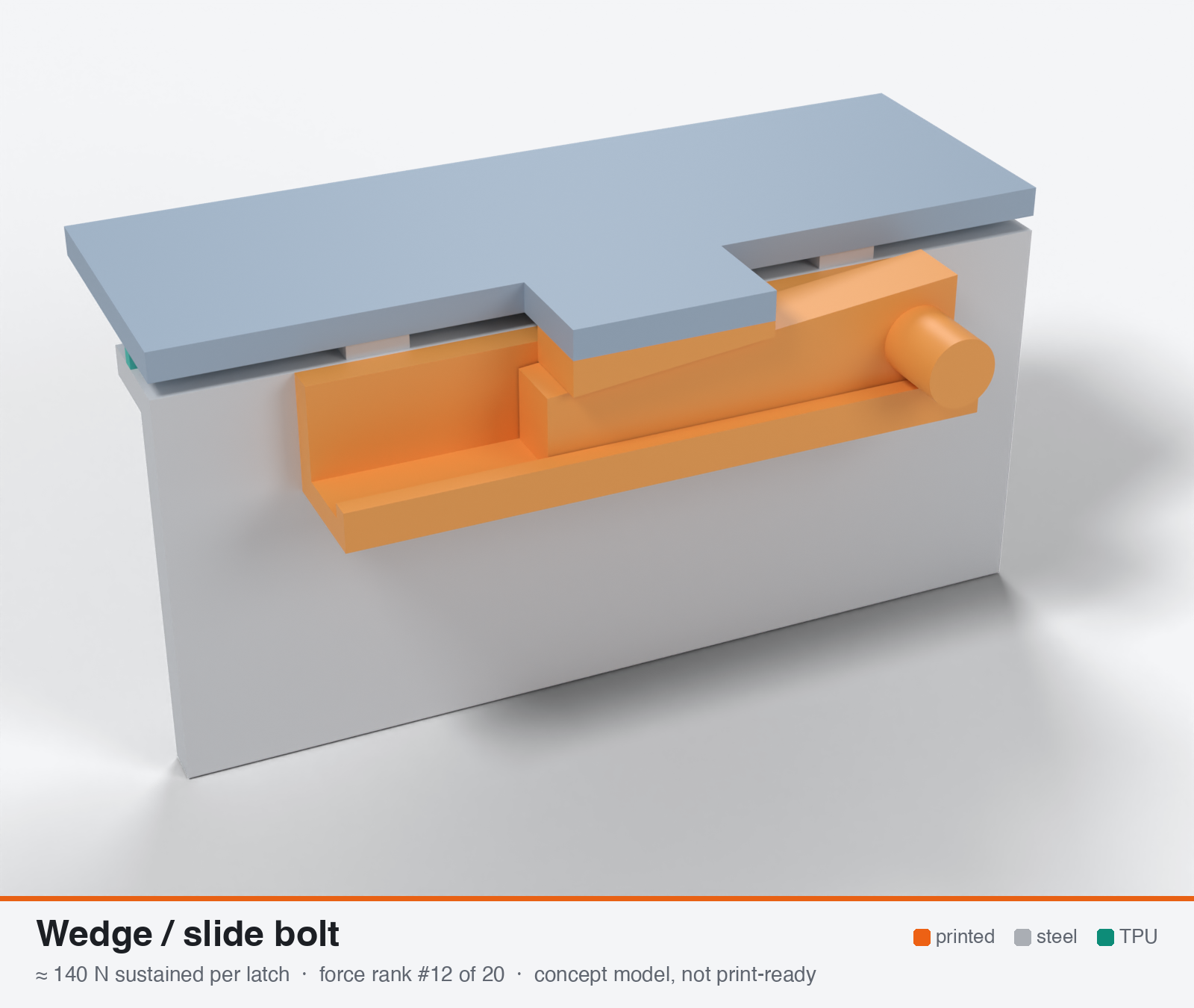
Wedge / slide-bolt latch (tapered wedge into tapered catch)
- Force rank
- 12 of 20
- Rank for outdoor sealing
- 9
- Latches for the reference lid
- 10–20
- Build
- Fully printed
- Hand force to close
- ≈ 170 N
- Adjustable preload
- yes
- Positive compression stop
- yes
- Force basis
- calculated
- Review verdict
- corrected
- Confidence
- low
Verdict: Cut from 200 N to the force a reasonable push can deliver. The wedge gives excellent stroke control (10:1) and recovers hot set, but it needs a separate pivoted tab or catch block anchor. Loose wedge, fretting and ice jams are the risks.
Why it ranks #9 for sealing: About 140 N (range 75-280) hand-limited, but the best stroke control of the non-screw types: 1 mm of squeeze needs 10 mm of travel, so tolerance and hot set are easy to take up. A jack screw raises it to 250-300 N. Anchoring the tab and catch block is the real limit. Loose wedge, fretting and ice jams hurt outdoor durability (5).
On this page
Parts
Per latch: 2 parts to print, 3 items to buy, 3 features printed into the box or lid and the TPU 85A seal. Parts marked † are not drawn in the 3D model. In the 3D gallery you can click a part to see where it sits. The last column links the print file, or an example of the part in a shop (see the shopping list).
| Part | Qty | Type | What to use | File or shop |
|---|---|---|---|---|
| Guide | 1 | ASA, flat on its back; pocket for the wedge tip and a bridge outboard of the catch | guide.stl | |
| Wedge | 1 | ASA, on its side so both sliding faces are smooth walls; 1:10 taper | wedge.stl | |
| Catch block | 1 | Printed with the lid | Hangs from the lid tab: 26 mm wide, 7.5 mm thick, with a 10.8 mm window whose floor matches the taper | lid-coupon.stl |
| Guide screws † | 2 | Buy | M3 × 10 A2/A4 socket screws (DIN 912) | Grobotronics |
| Square nuts † | 2 | Buy | M3 square nuts (DIN 562), dropped down the channels in the box wall | Grobotronics |
| Detent (optional) † | 1 | Buy | M4 A4 spring plunger | Leschhorn |
| Hard stops | 2 | Printed with the box | Pads on the rim either side of the latch, 1.6 mm tall: 0.8 mm below the free seal | box-coupon.stl |
| Nut channels | 2 | Printed with the box | Inside pillar with a 5.7 × 2.0 mm channel per nut, open on the rim outside the seal; blind 3.4 mm screw holes, so no path into the box | box-coupon.stl |
| Seal strip | 1 | Seal (TPU 85A) | TPU 85A, 1.5 × 3.4 mm, in a 1.8 × 1.0 mm groove in the rim; the latch squeezes it 0.8 mm | seal-strip.stl |
Print files
Download all print files for this latch (ZIP, 58 kB)
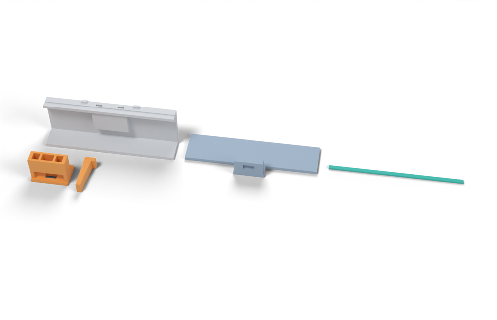
Print version: Redrawn so the wedge pulls the lid down: it slides in toward the wall through a window in a catch that hangs from the lid tab, with its top against the guide on the box. In the concept model the wedge pushes the catch up.
Print in ASA (TPU 85A for the seal), 0.2 mm layers, at least 4 walls; settings and the clearances used are in print/README.md. The parts are already turned the right way up for printing. The box and lid coupons are short test sections with this latch's box-side and lid-side features, so you can try the latch before building it into your own enclosure.
| File | Material | Qty | Size (mm) | How to print |
|---|---|---|---|---|
| guide.stl | ASA | 1 | 33 × 22 × 26 | Flat on its back, no supports. The wedge slides in toward the wall; its top bears on the bridge and the pocket ceiling. 2 × M3 × 10 into the box. |
| wedge.stl | ASA | 1 | 10 × 33 × 10 | On its side so both sliding faces are smooth walls, no supports. Taper 1:10; pushing it in 14 mm pulls the catch down 1.4 mm. |
| box-coupon.stl | ASA | 1 | 120 × 24 × 41.6 | Upright, no supports. A section of box wall with this latch's box-side features: seal groove, hard stops, and an inside pillar with nut channels. Push an M3 square nut down each of the 2 channels in the rim before fitting the screws. Copy these features into your own box. |
| lid-coupon.stl | ASA | 1 | 120 × 41 × 17.1 | Upside down. A section of lid with this latch's lid-side features. Copy them into your own lid. |
| seal-strip.stl | TPU 85A | 1 | 120 × 3.4 × 1.5 | TPU 85A, 100 % infill, lying on its side. Press it into the rim groove: it stands 2.4 mm proud and the latch squeezes it 0.8 mm, until the lid lands on the hard stops. |
All printed parts in their assembled positions, for CAD: wedge-slide-bolt.step.
How it works
A flat tapered key (slope about 1:10) is pushed through a window in a tab that hangs through a catch block; the key wedges between the window edge and the catch face and pulls the lid down. At 1:10 the wedge self-locks against dry plastic friction (tan 5.7 deg = 0.10 < mu 0.15-0.25) and the 10:1 travel ratio gives very fine control of gasket squeeze. Printed flat with the pull load in-plane it needs no hardware. The ideal 10:1 force ratio is mostly lost to friction on the two faces, so hand push, not taper, sets the force.
Mechanical advantage
Ideal 1/tan(alpha) = 10:1 for a 1:10 taper (alpha = 5.71 deg). With friction on both faces the real force ratio F/P = 1 / (tan(phi2) + tan(alpha + phi1)) is about 1.6:1 at mu 0.25, 2.5:1 at mu 0.15 and 3.3:1 at mu 0.10 (own calc); a shallower taper barely helps because friction dominates. Release force is about 0.40 F (mu 0.25) or 0.20 F (mu 0.15). A captive M4 jack screw (nut factor 0.2) would add a further leverage of about 1250 N per Nm of screw torque.
What limits the force
Printed tab geometry: the end-cap beam below the window (bending in-plane) sets the sustained force, the net section of the tab legs at the window corners sets the break load; the practical ceiling is also the hand push (about 140-210 N needed for 340 N of clamp).
Analyst's calculation
Analyst's sustained estimate: 250–500 N, typical 340 N; peak 1400 N.
ASSUMED PART (own): wedge key 10 mm wide x 40 mm long, 6 mm thick tapering to 2 mm (1:10, alpha 5.71 deg), sliding through a 10 mm wide window in a tab 26 mm wide x 8 mm thick; the key bears on the catch block's face above and on the 10 mm tall end cap of the window below. ASA, tab printed flat so the pull load is in the layer plane, 5-6 perimeters, 0.2 mm layers, key printed on its side with the taper profile in the XY plane so bearing loads are in-plane.
- Mechanical advantage with friction (own calc using P = F [tan(phi2) + tan(alpha + phi1)], friction 0.25 / 0.15 from https://elesa.com/en/elesab2bstoreca/Clamping-handles--Cam-levers--GN9272-A--d1): ideal 10; mu 0.25 both faces: P/F = 0.61, ratio 1.6; mu 0.15: 0.40, ratio 2.5; mu 0.10: 0.30, ratio 3.3. Pull-out force F [tan(phi2) + tan(phi1 - alpha)] = 0.40 F at mu 0.25 and 0.20 F at mu 0.15. Self-locking criterion tan(alpha) < mu (https://en.wikipedia.org/wiki/Wedge) holds for dry plastic but fails for wet, waxed or PTFE faces (mu under 0.1), and self-holding tapers in machining use only about 1.5 deg per side while steep 7:24 tapers self-release (https://en.wikipedia.org/wiki/Machine_taper); a 1:10 plastic wedge is in between, so add a detent.
- Structure (sustained, in-plane allowable 3 / 4 / 6 MPa for ASA at 60-70 C per the project brief, x 0.8 notch factor): (a) end-cap beam, span 10 mm, section 10 x 8 mm: Z = 133 mm3, M = F L / 8 = 1.25 F, sigma = 0.0094 MPa per N, giving 255 / 340 / 510 N (weakest, sets the result); (b) tab legs 2 x 8 x 8 = 128 mm2 net: 307 / 410 / 614 N; (c) window-edge bearing 10 x 8 = 80 mm2 at 8-10 MPa: 640-800 N. Peak at room temperature: legs 128 mm2 x about 37-44 MPa XY tensile (ASA datasheets, https://cdn.shopify.com/s/files/1/0603/6609/files/PolyLite_ASA_TDS_V5.1.pdf) / Kt 2.5 = about 1.4-1.6 kN; I report 1400 N.
- Hand drive (assumption, own): a thumb pushes about 50-100 N, giving 80-250 N of clamp at the real ratios 1.6-2.5; reaching 340 N needs about 140-210 N push (palm heel or a tap). An M4 jack screw pushing the wedge makes P = T / (0.2 x 4 mm); only about 0.15 Nm is needed for 340 N of clamp, whereas 1 Nm would give 2-3 kN and break the tab, so torque-limit it.
- Gasket stroke: at 1:10 each 1 mm of squeeze needs 10 mm of wedge travel, so +/-0.5 mm of wedge position is only +/-0.05 mm of squeeze, which handles the 0.2-0.75 mm stroke of a 3 mm bead far better than a fixed-travel latch. Stepped notches or a screw give an adjustable preload and a bottoming stop gives a defined squeeze.
- Result: sustained 250 / 340 / 500 N; peak 1400 N. At 100 mm latch pitch this is 2.5 / 3.4 / 5.0 N/mm, covering the 2-4 N/mm design window. No test data for a printed wedge latch exists; this is reasoning only. Further web searches were blocked (search budget exhausted).
Adversarial review
I reproduced the wedge ratios (1.64 / 2.48 / 3.31), the release forces, the end-cap beam (Z = 133 mm3, M = 1.25 F) and the leg net section (128 mm2). The analyst's structural arithmetic is internally consistent apart from the peak. The problem is what the 340 N represents. It is the beam limit for a 10 mm cap with a distributed load, not what a hand can push, and it ignores the pin/catch anchorage, which gives 256-400 N for an M4/M5 pin at the brief's 8-10 MPa bearing. Pushing 50-100 N at the real ratio gives 80-250 N, so I set typical 200 N (about 41 percent below the analyst), low 100 N, high 400 N, peak 1200 N. This is a calculation with no test data; the analyst found no existing printed wedge design, and my search budget was exhausted so I could not look for any. Source checks: Wikipedia Wedge fetched; it gives ideal MA = 1/tan(alpha) and a binding condition on the angle versus friction, which the analyst quoted correctly. Wikipedia Machine taper fetched; Morse about 1.49 deg per side, and 7:24 is steep and self-releasing; the analyst's '1.4-2.3 deg per side' is close. Elesa friction values confirmed. The Polymaker XY range is a misattribution (43.8 MPa is Polymaker's, 37 is Bambu's). Ultrafuse set 26/52 percent confirmed from the local PDF read. Wedge and cotter analysis is textbook (classical cotter joints: rod tension at the slot, end-cap bending and shear, bearing), but the printed-plastic allowables of 3 / 4 / 6 MPa are the brief's untested rule of thumb for ASA at 60-70 C.
Issues raised:
- Wedge ratios confirmed: F/P = 1.64 (mu 0.25), 2.48 (mu 0.15), 3.31 (mu 0.10), with frictionless-guide formula P = F[tan phi + tan(alpha+phi)]. Release force is 0.40 F / 0.20 F, also confirmed.
- The 340 N typical is a structural number, not a deliverable one. It needs 207 N of push at mu 0.25 (136 N at mu 0.15). The analyst's own 'thumb 50-100 N' gives 80-250 N. The brief's comfortable range is 20-50 N, and release then needs 70-135 N pull. Applying the same hand-limited logic used for the cap and bayonet, typical is about 200 N, low about 100 N. Above about 250 N a tap, palm-heel or jack screw is needed (hardware, and torque-limit it).
- Structural check reproduced: end cap beam 0.0094 MPa per N (255 / 340 / 510 N at 3 / 4 / 6 MPa x 0.8) and tab legs 128 mm2 (307 / 410 / 614 N). These assume a uniform load across the 10 mm cap. If the wedge loads the cap centrally (M = F L/4) the cap numbers halve to 128 / 170 / 255 N. The peak arithmetic is also not reproducible: 128 mm2 x 37-44 MPa / Kt 2.5 = 1.9-2.25 kN, not 1.4-1.6 kN.
- The attachments are not analysed, and they are the likely limit. The tab cannot be printed flat if it is integral with a lid printed flat, so a flat tab means a separate part with a steel pivot pin or screw, which contradicts 'no hardware'. A pin M4 in an 8 mm printed tab at 8-10 MPa bearing allows only 256-320 N (M5: 320-400 N). The catch block is a cantilever shelf loaded across layers when the body is printed upright. These limit sustained to about 250-320 N and peak to about 1.2 kN, hence 220-300 N is the realistic ceiling.
- The self-locking statement is too pessimistic. For a wedge between two friction faces it holds when alpha < phi1 + phi2, not tan(alpha) < mu. At mu 0.10 the 5.7 deg wedge still holds (release force 0.1 F). The 7:24 machine taper (16.6 deg included) self-releases, consistent with 2 phi for steel. So wet or waxed faces are not the failure mode claimed. Real risks are fretting, dirt/ice jams and a lost wedge.
- Stroke control is the real advantage: 1 mm of squeeze needs 10 mm of travel, so +/-0.5 mm of position is +/-0.05 mm squeeze, and a recovered position fixes TPU set. At about 200 N and 100 mm pitch (2.0 N/mm) it just reaches the lower edge of the 2-4 N/mm window; 8 latches on a 700 mm path give about 2.3 N/mm. Seal suitability 6 is kept as the best of the four.
- Scores adjusted: durability 6 to 5 (unanalysed anchors, loose part, fretting under sustained hot load), printability 8 to 7 (a separate tab plus pivot or inserts), usability 5 to 4 (push and release forces well above 20-50 N, tethered loose wedge, no tests).
Calibration adjustments
- sustained_N.typical: 200 (reviewer; range 100-400) → 140 (range 75-280). Same hand-limited rule as the cap and bayonet: input at or near the 50 N comfort limit. The reviewer's own 1.64-2.48 push ratio gives 82-124 N from 50 N, so 200 N needs 80-125 N of push. The catch block is also a cantilever loaded across layers, as in the vise-action latch.
Preload retention outdoors
Fair. The wedge itself holds without back-off if the faces stay dry (self-locking), and its 10:1 travel means a loss of preload from TPU set (30-58 percent at 70 C, https://www.dream3d.co.uk/wp-content/uploads/2022/12/Ultrafuse_TPU_85A_TDS_EN_v2.5.pdf) can be recovered by driving the wedge a few mm further (stepped teeth or a screw). The ASA wedge faces and tab end cap also creep and relax under sustained hot load, and fretting wears the faces. A series spring (steel wave washer or flexible tab) would cut the TPU loss to about 10 percent (own calc, method from the brief).
Materials
ASA (default). UV-stabilised PC would raise the in-plane sustained limit about 1.3-1.5x (own judgement, unmeasured). PETG is marginal at 60-70 C; PETG-CF does not fix that. A stainless wear plate or PTFE tape on the wedge faces stabilises friction; avoid PA6-CF outdoors.
Hardware notes from the research
None required (fully printed). Optional: M4 A4 jack screw with captive nut to drive and lock the wedge, stainless or PTFE wear liner on the wedge faces, A4 spring plunger as a detent, wave washer as a series spring.
Design guidelines
- Taper 1:10 to 1:15 (alpha 3.8-5.7 deg); do not go steeper than 1:8 or friction no longer holds. Smooth, ironed wedge faces with a dwell step or a detent notch every 1 mm of squeeze.
- Tab at least 8 mm thick, 26 mm wide, window 10 mm wide with end cap at least 10 mm tall and all window corners R at least 3 mm; legs at least 8 mm each. Print the tab flat so the pull load is in the layer plane.
- Print the wedge on its side with the taper profile in the XY plane; 5-6 perimeters, 0.16-0.2 mm layers.
- Set the wedge end-stop so full insertion gives 20-25 percent squeeze (about 0.75-0.8 x free bead height) and add a printed hard stop beside each latch.
- Add a detent or an M4 A4 jack screw to hold the wedge when wet, waxy or vibrated (mu under 0.1); torque-limit a jack screw to about 0.15 Nm.
- Use a pull tab or hole of at least 8 mm on the wedge for removal, since release takes 0.2-0.4 x clamp force (about 70-135 N).
- Keep the load line through the centre of the tab to limit the couple on the wedge; one wedge per tab, with latch pitch up to about 100 mm for a 2-4 N/mm gasket.
- Tether the wedge so it cannot be lost.
Failure modes
- End-cap beam cracks or legs tear at window corners (peel and brittle cracking in the cold).
- Wedge backs out in vibration or on wet or waxed faces (mu under 0.1), or when the TPU springs back.
- Face creep, fretting and wear lose preload; dirt, sand or ice jams the wedge.
- Over-driving with a hammer or jack screw cracks the tab.
- Cocking from the offset couple gives uneven squeeze at one end of the wedge.
- Wedge is lost if it is not tethered.
Evidence gathered in the sweep
SUSTAINED (own est., 10 mm wide ASA wedge): 100-300 N; PEAK ~400-900 N. NO PUBLISHED LOAD DATA FOUND. Friction coefficients used (plastic/plastic 0.25, plastic/steel 0.15) are from the Elesa page I verified https://elesa.com/en/elesab2bstoreca/Clamping-handles--Cam-levers--GN9272-A--d1 . The Firgelli toggle-latch page cited by the industrial researcher as wedge background does not mention wedges, so I do not rely on it. The web-search budget ran out before I could source a wedge latch. CONFIDENCE: low (reasoning only).
Sources
- Wikipedia: Wedge — Fetched: ideal MA = 1/tan(alpha); binding (self-locking) when tan(alpha) < mu
- Wikipedia: Machine taper — Fetched: self-holding Morse and Jacobs tapers about 1.4-2.3 deg per side versus self-releasing steep tapers (7:24)
- Elesa GN 927.2 page (friction coefficients) — Fetched: plastic/plastic 0.25, plastic/steel 0.15
- Polymaker PolyLite ASA datasheet — ASA XY tensile figures as given in the project brief, not re-fetched
- Ultrafuse TPU 85A datasheet — Compression set 26 / 52 percent figures from the project brief, not re-checked
Sources the reviewer flagged (dead, blocked or misdescribed):
- https://cdn.shopify.com/s/files/1/0603/6609/files/PolyLite_ASA_TDS_V5.1.pdf - cited for 'XY tensile about 37-44 MPa'; Polymaker's XY value is 43.8 MPa (Z 32 MPa), 37 MPa is Bambu's; specimen conditions (70 C chamber, 100 percent infill) flatter real parts.
- https://en.wikipedia.org/wiki/Wedge - live, but the cited tan(alpha) < mu self-locking criterion is for a single friction face; with friction on both faces it is alpha < phi1 + phi2, so the 'fails below mu 0.1' conclusion drawn from it is wrong.
- No existing printed wedge-latch design, force test or IP data was found or cited; the number is reasoning only.