No. 16 of 20 · Rectangular lids
Rotary cam lock
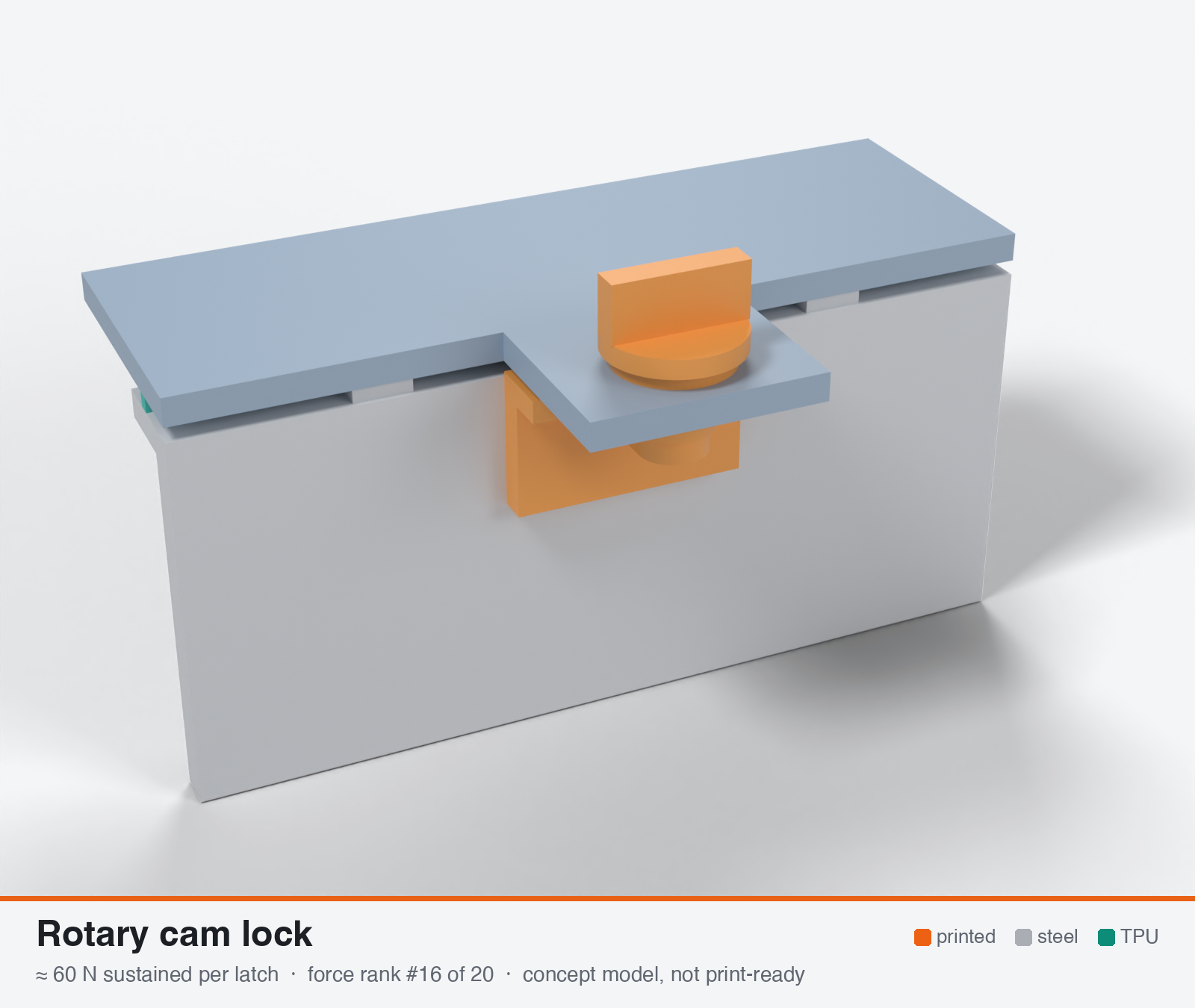
Rotary cam lock / tapered quarter-turn latch with little or no draw-down
- Force rank
- 16 of 20
- Latches for the reference lid
- 24–47
- Build
- Printed + steel hardware
- Hand force to close
- ≈ 16 N
- Adjustable preload
- no
- Positive compression stop
- no
- Force basis
- estimated
- Review verdict
- confirmed
- Confidence
- medium
Verdict: The thumb can overload the printed tongue (165-225 N at 0.8 Nm). The tongue limits it to about 25-100 N. No stop, and no way to re-tighten. A 700 mm path would need 15-35 cams.
On this page
Parts
Per latch: 3 parts to print, 4 items to buy, 3 features printed into the box or lid and the TPU 85A seal. Parts marked † are not drawn in the 3D model. In the 3D gallery you can click a part to see where it sits. The last column links the print file, or an example of the part in a shop (see the shopping list).
| Part | Qty | Type | What to use | File or shop |
|---|---|---|---|---|
| Cam lock body with knob | 1 | ASA, knob down; a hex on the end of the shank drives the tongue | cam-lock-body.stl | |
| Tongue | 1 | ASA, flat; 8 mm thick, 14 mm wide, reaching 8.8 mm from the shaft, with a hex socket for the body | tongue.stl | |
| Keeper | 1 | ASA, on its end; the ledge tapers 0.8 mm over the last part of the turn, with a stop block | keeper.stl | |
| Screw, washer and nyloc nut † | 1 | Buy | M5 × 25 A2/A4 socket screw (DIN 912) from the top, with a washer and nyloc nut under the tongue | M5 screw · washer · M5 nyloc |
| Keeper screws † | 2 | Buy | M3 × 10 A2/A4 socket screws (DIN 912) | Grobotronics |
| Square nuts † | 2 | Buy | M3 square nuts (DIN 562), dropped down the channels in the box wall | Grobotronics |
| Detent (optional) † | 1 | Buy | M4 A4 spring plunger | Leschhorn |
| Lid tab with hole | 1 | Printed with the lid | 8.5 mm hole for the body | lid-coupon.stl |
| Hard stops | 2 | Printed with the box | Pads on the rim either side of the latch, 1.6 mm tall: 0.8 mm below the free seal | box-coupon.stl |
| Nut channels | 2 | Printed with the box | Inside pillar with a 5.7 × 2.0 mm channel per nut, open on the rim outside the seal; blind 3.4 mm screw holes, so no path into the box | box-coupon.stl |
| Seal strip | 1 | Seal (TPU 85A) | TPU 85A, 1.5 × 3.4 mm, in a 1.8 × 1.0 mm groove in the rim; the latch squeezes it 0.8 mm | seal-strip.stl |
Print files
Download all print files for this latch (ZIP, 79 kB)
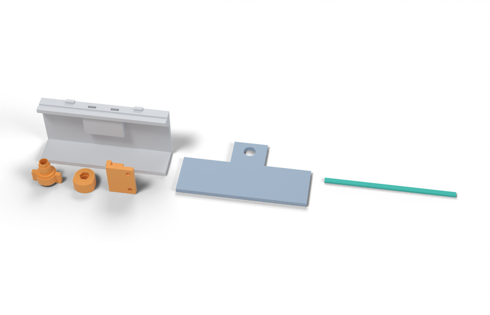
Print version: The tongue is 8 mm thick, as the guidelines ask, and the keeper's ledge tapers 0.8 mm over the last part of the turn.
Print in ASA (TPU 85A for the seal), 0.2 mm layers, at least 4 walls; settings and the clearances used are in print/README.md. The parts are already turned the right way up for printing. The box and lid coupons are short test sections with this latch's box-side and lid-side features, so you can try the latch before building it into your own enclosure.
| File | Material | Qty | Size (mm) | How to print |
|---|---|---|---|---|
| cam-lock-body.stl | ASA | 1 | 20 × 14 × 19 | Knob down, no supports. The hex on the end of its shank drives the tongue; an M5 × 25 socket screw from the top, with a washer and nyloc nut under the tongue, holds them together. |
| tongue.stl | ASA | 1 | 14 × 15.8 × 8 | Flat, no supports; 8 mm thick, with a hex socket for the body's shank. |
| keeper.stl | ASA | 1 | 19.2 × 7 × 24 | On its end, no supports. The ledge underside tapers 0.8 mm over the last part of the turn; the block is the stop. 2 × M3 × 10 into the box. |
| box-coupon.stl | ASA | 1 | 90 × 24 × 41.6 | Upright, no supports. A section of box wall with this latch's box-side features: seal groove, hard stops, and an inside pillar with nut channels. Push an M3 square nut down each of the 2 channels in the rim before fitting the screws. Copy these features into your own box. |
| lid-coupon.stl | ASA | 1 | 90 × 50 × 3 | Flat, top up. A section of lid with this latch's lid-side features. Copy them into your own lid. |
| seal-strip.stl | TPU 85A | 1 | 90 × 3.4 × 1.5 | TPU 85A, 100 % infill, lying on its side. Press it into the rim groove: it stands 2.4 mm proud and the latch squeezes it 0.8 mm, until the lid lands on the hard stops. |
All printed parts in their assembled positions, for CAD: rotary-cam-lock-simple.step.
How it works
A quarter-turn cam tongue (or tapered tongue) on a shaft turns behind the frame or panel; a plain tongue gives no defined compression, a roller or tapered cam draws the panel down by up to about 2 mm (Southco E5 roller cam). It is easy to print on a stainless shaft, but the force path is a thin cantilevered tongue in bending with a line contact, so it creeps and carries little load. Fine for dust or splash with foam or thin-lip gaskets, or as a secondary lock, not for a TPU 85A rib.
Mechanical advantage
Taper ramp: F = T / (r tan(alpha + phi)). For r = 12 mm and an 8 deg ramp, T/F = 4.9 mm at mu 0.25 and 3.6 mm at mu 0.15 (frictionless 1.7 mm). With an 18 mm thumb-knob radius the force ratio is about 3.7-5:1 (T handle at 40 mm radius about 8-11:1). A plain cam with no taper has effectively no draw-down. (own calc)
What limits the force
The printed tongue in bending (about 0.05-0.2 MPa per newton depending on thickness; 3-6 MPa sustained allowable gives 25-100 N) and the hub/shaft bearing, not the hand: a thumb knob can easily deliver 165-225 N at 0.8 Nm and overload the tongue.
Analyst's calculation
Analyst's sustained estimate: 25–100 N, typical 60 N; peak 250 N.
ASSUMED PART (own): printed cam tongue 14 mm wide x 8 mm thick, contact 8 mm from the hub root and r = 12 mm from the shaft axis, 8 deg taper, on an M5 A4 stainless screw or D-shaft, thumb knob radius 18 mm (hand torque 0.5-1 Nm; up to 1.5 Nm with a T handle). Printed with the shaft axis horizontal so that in the lock position the tongue lies in the layer plane and bends in-plane.
- Torque to force: F = T / (r tan(alpha + phi)). Friction values 0.25 plastic/plastic and 0.15 plastic/steel (https://elesa.com/en/elesab2bstoreca/Clamping-handles--Cam-levers--GN9272-A--d1). r tan(alpha+phi) = 4.9 mm (mu 0.25), 3.6 mm (mu 0.15); frictionless 1.7 mm. At 0.8 Nm that is 165-225 N, so the hand can overload the tongue.
- Tongue as a cantilever (own): sigma = 6 F l / (b h^2) = 6 x 8 / (14 x 64) = 0.054 MPa per N. Sustained in-plane allowable 3 / 4 / 6 MPa (project brief rule for ASA at 60-70 C) x 0.85 root-fillet factor gives F = 48 / 64 / 95 N. A thinner 4-6 mm tongue (typical of printed cams) has 0.1-0.2 MPa per N, i.e. only 15-40 N. I therefore report sustained 25 / 60 / 100 N. Peak: in-plane XY tensile about 37-44 MPa for ASA datasheets (Polymaker https://cdn.shopify.com/s/files/1/0603/6609/files/PolyLite_ASA_TDS_V5.1.pdf) / Kt 1.5 gives about 20 MPa, so about 370 N for the 8 mm tongue; hand-limited at 1.5 Nm = 310 N; I report 250 N as a margin-adjusted peak.
- Context: a metal eccentric clamping lever (Elesa GN 927.2, size 44) gives 1450 N for 75 N hand force (https://elesa.com/en/elesab2bstoreca/Clamping-handles--Cam-levers--GN9272-A--d1), which shows how far a simple quarter-turn printed cam is from a true clamp; Southco E5 roller cam compresses up to 2 mm of light-duty gasket and its Flush Cup meets NEMA 4 / IP65 but no holding force is stated (https://brandspurng.com/2020/09/23/southco-introduces-new-product-extensions-to-its-successful-e5-cam-latch-series/). A stainless cam on the same shaft would carry several hundred N, but then it is not printed.
- Seal check: at 2-4 N/mm a 60 N cam can serve only about 15-30 mm of gasket, so a 200 x 150 mm lid would need 25-45 cams. Further web searches were blocked (search budget exhausted); the MakerWorld printed quarter-turn latch page returned HTTP 403, so no printed-cam force data was found.
Adversarial review
Independent recalculation: cam T/F 3.56-4.86 mm; tongue stress 0.0536 MPa per N; sustained allowables 3 / 4 / 6 MPa x 0.85 give 48 / 63 / 95 N. The analyst's typical of 60 N is reproduced within 5 percent. Source checks: the Elesa GN 927.2 page is live and states mu 0.25 plastic/plastic and 0.15 plastic/steel. For size 44 it lists 75 N manual force and 1450 N clamping force, as claimed (the page's extracted table has an unlabeled column with 33, which I ignored). The Southco/brandspurng page is live: roller cam gives up to 2 mm light-duty compression, Flush Cup meets NEMA 4 and IP65 with E5 or E3 latches, and no holding force is stated. The Polymaker TDS was read locally: XY tensile is 43.8 MPa, bending strength XY 73.4 MPa. The analyst's '37-44 MPa for Polymaker' is a misattribution, since 37 MPa is the Bambu figure from the brief. Specimens were 70 C chamber, 100 percent infill, and the sheet says not for design. The MakerWorld quarter-turn latch page is HTTP 403 and unverifiable; no printed-cam force data exists in the sources I could read. My search budget was exhausted, so I could not search for more. A cam latch is the weakest sealing mechanism here, and the force is limited by the tongue, not the hand. Confirmed, with peak raised.
Issues raised:
- Taper arithmetic confirmed: r tan(alpha+phi) = 4.86 mm (mu 0.25) and 3.56 mm (mu 0.15), so 0.8 Nm gives 165-225 N. A thumb knob can therefore overload the tongue, as the analyst said.
- Tongue cantilever confirmed: sigma = 0.0536 MPa per N for 14 x 8 mm at 8 mm reach. With 3 / 4 / 6 MPa x 0.85 that is 48 / 63 / 95 N, which supports 25 / 60 / 100 N. The typical 60 N assumes an 8 mm thick tongue; thin 4-6 mm cams (the common printed design) give only 15-40 N.
- Peak is understated. The analyst's 250 N is a 'margin-adjusted' figure, but peak was meant to be the breaking load. 20-27 MPa in-plane (datasheet XY flexural strength is 73 MPa) divided by the sigma-per-N coefficient gives 370-500 N, and the hub, fillet and shaft bearing reduce that. I use 350 N. Peak is separate from sustained and does not change the ranking.
- Even 100 N serves only 25-50 mm of gasket at 2-4 N/mm, so a 700 mm path would need 15-35 cams. Seal suitability 2 stands. The taper over 90 deg (about 2.65 mm of draw-down) does give fine stroke control, but no hard stop is defined by the cam itself.
- The shaft hole bears on a printed hub: an M5 washer bears on about 55 mm2, so at 100 N the bearing is about 2 MPa, which is fine. Creep of the printed hole around the steel shaft is a real long-term loss but is not quantified.
- Zinc-plated shafts rust within months; specify A4. The Southco E5 cam latch figures (up to 2 mm compression, Flush Cup NEMA 4 / IP65, no holding force) confirmed from the cited page.
Preload retention outdoors
Poor. The cam is a rigid fixed-travel element on a thin printed tongue: TPU set (30-58 percent force loss at 70 C, https://www.dream3d.co.uk/wp-content/uploads/2022/12/Ultrafuse_TPU_85A_TDS_EN_v2.5.pdf) combines with tongue bending creep and line-contact wear, so little of the original preload survives hot summers. It cannot be re-tightened.
Materials
ASA for the cam and knob; PC (UV-stabilised) improves tongue creep margin about 1.3-1.5x (own judgement). A stainless or die-cast cam is the realistic way to more than about 100 N. Avoid PETG and PA6-CF outdoors.
Hardware notes from the research
M5 A4 stainless screw or D-shaft, A4 washer, A4 nyloc or lock nut; optional stainless cam or roller; optional spring plunger detent. A threaded stud with lock nut would make the cam height adjustable.
Design guidelines
- Tongue at least 8 mm thick and 14 mm wide with R at least 3 mm fillet at the hub; reach no more than 12 mm from the shaft axis.
- Print with the shaft axis horizontal so that the tongue in the lock position lies in-plane, not across layers.
- Taper ramp 3-8 deg over the last 90 deg of rotation, with a rotation stop and a detent bump; a roller or low-friction face reduces wear.
- Metal shaft or stainless bush in the hub (A4 M5); never let the printed hole bear on the thread.
- Use only with a light gasket (thin lip or foam) or put one latch every 15-30 mm.
- Add a separate printed hard stop beside each latch, since the cam itself defines no squeeze.
- For loads over about 100 N substitute a stainless cam or use another mechanism.
Failure modes
- Tongue creeps or cracks at the hub fillet.
- Printed hole creeps around the steel shaft, so the cam drops and loses preload.
- Cam rotates back with vibration without a detent.
- Line contact wear; zinc-plated shafts rust within months outdoors (12-72 h salt spray).
- Gasket leaks because force is simply too low.
- Cold brittleness at sharp corners of the tongue.
Existing designs and commercial references
- MakerWorld quarter-turn latch (compression capable) — Four printed parts, 90 deg turn, taper compression, default for 2.5 mm acrylic panel; no force data (per lead; HTTP 403 to my fetch)
- Southco E5 cam latch extensions (metal reference) — Roller cam up to 2 mm compression; Flush Cup accessory NEMA 4 / IP65; no holding force stated (fetched)
Evidence gathered in the sweep
SUSTAINED (own est.): printed 20-60 N, steel-shaft cam <100 N; PEAK 100-250 N. EVIDENCE: Southco E5 roller cam up to 2 mm compression, Flush Cup accessory NEMA 4/IP65 https://brandspurng.com/2020/09/23/southco-introduces-new-product-extensions-to-its-successful-e5-cam-latch-series/ ; MakerWorld quarter-turn latch (compression capable): 4 printed parts, 90 degree turn, taper compression, 2.5 mm acrylic default panel, no force data https://makerworld.com/models/3070853 ; E5 316 stainless cam latch 670 N rating is for the metal part (via Gripwell/Southco sheet, search text). CONFIDENCE: low.
Sources
- Southco E5 cam latch extensions — Fetched: up to 2 mm light-duty compression, NEMA 4 / IP65 for the Flush Cup; no load rating given
- Elesa GN 927.2 page — Fetched: friction coefficients (0.25 / 0.15) and metal cam-lever table (75 N hand gives 1450 N clamp for size 44)
- Polymaker PolyLite ASA datasheet — ASA XY and Z tensile figures as given in the project brief, not re-fetched
- MakerWorld quarter-turn latch — Not retrievable (HTTP 403); description via the lead's search summary
- Ultrafuse TPU 85A datasheet — Compression set figures from the project brief, not re-checked
Sources the reviewer flagged (dead, blocked or misdescribed):
- https://makerworld.com/models/3070853 - HTTP 403, unverifiable (compression-capable 90 deg latch, no force data).
- https://cdn.shopify.com/s/files/1/0603/6609/files/PolyLite_ASA_TDS_V5.1.pdf - cited for 'XY tensile about 37-44 MPa'; Polymaker's own XY value is 43.8 MPa (Z 32 MPa); 37 MPa is Bambu's figure. Specimen conditions (70 C chamber, 100 percent infill) flatter real parts.