No. 06 of 20 · Rectangular lids
Vise-action (lift-and-turn) screw-cam
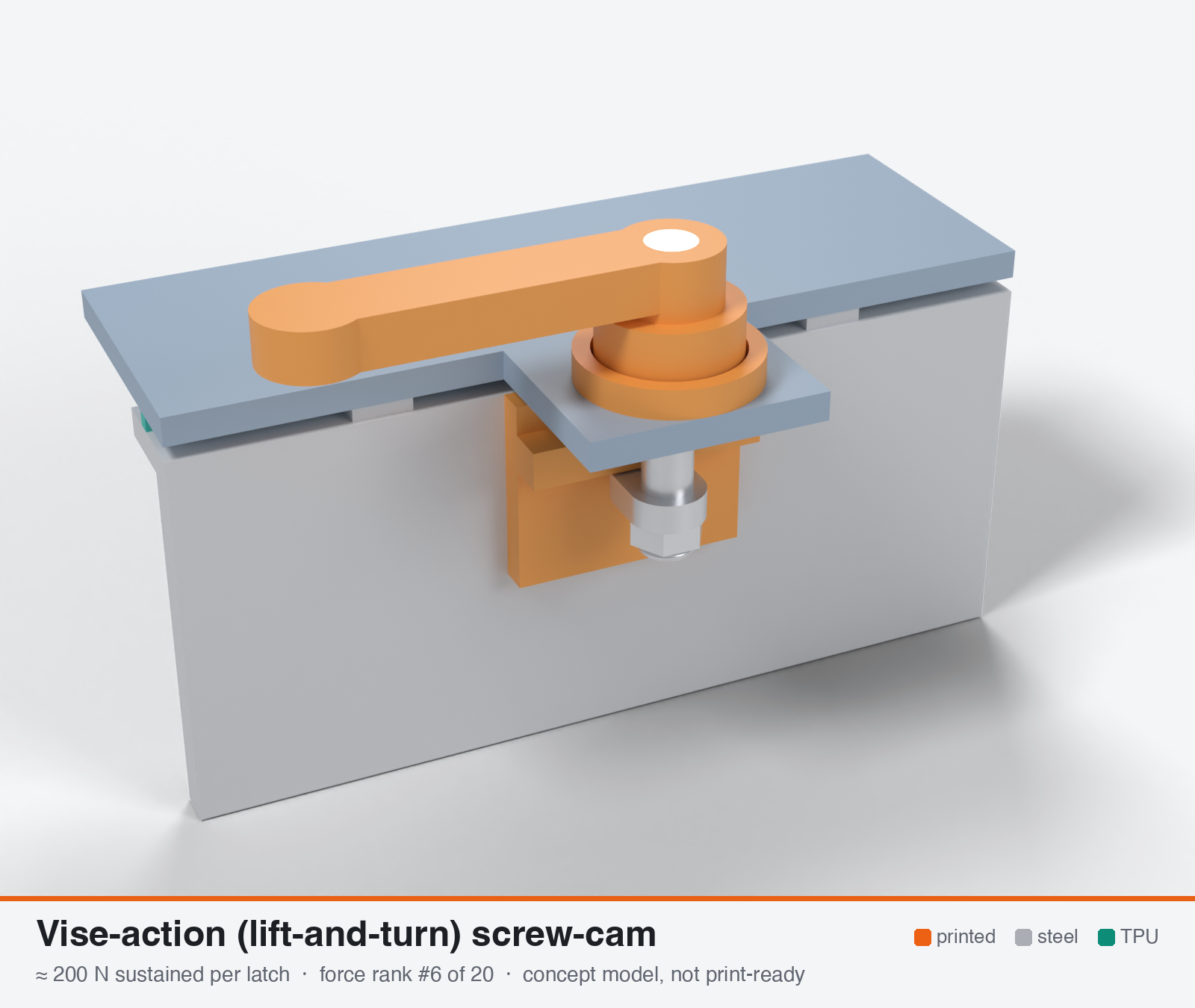
Vise-action / lift-and-turn compression latch (cam plus screw take-up)
Model note: The 3D model puts the ramp in a cup under the handle hub: a quarter turn lets the hub drop 1.5 mm, which lowers the pawl off the keeper lip as it swings clear. The pawl's end is rounded so it misses the keeper plate while it turns.
- Force rank
- 6 of 20
- Rank for outdoor sealing
- 8
- Latches for the reference lid
- 7–14
- Build
- Mostly hardware
- Hand force to close
- ≈ 21 N
- Adjustable preload
- yes
- Positive compression stop
- yes
- Force basis
- estimated
- Review verdict
- corrected
- Confidence
- low
Verdict: Limited by the keeper ledge loaded across layers (120-240 N). Adjustable, with a positive stop and about 22 N hand force. Printed helical ramps wear. Force scatter is about 40 % without a spring.
Why it ranks #8 for sealing: About 200 N (range 100-350), adjustable by the stud nut, with a positive stop and about 22 N hand force. Limited by the keeper ledge across layers, and printed ramps wear and back-drive under ice or dirt. Needs a wave spring or Belleville plus a 2.5-3 mm ramp rise to hold the force. Only worthwhile with a steel keeper.
On this page
Parts
Per latch: 3 parts to print, 5 items to buy, 3 features printed into the box or lid and the TPU 85A seal. Parts marked † are not drawn in the 3D model. In the 3D gallery you can click a part to see where it sits. The last column links the print file, or an example of the part in a shop (see the shopping list).
| Part | Qty | Type | What to use | File or shop |
|---|---|---|---|---|
| Handle with hub | 1 | ASA, upside down; M5 nut pocket in the top, two lugs underneath | handle.stl | |
| Ramp cup | 1 | ASA, upright; two 1.5 mm ramps over 90°, a 30° flat dwell and a stop; closes clockwise | ramp-cup.stl | |
| Keeper with lip | 1 | ASA, on its end so the lip bends along the layers | keeper.stl | |
| Stud | 1 | Buy | M5 × 40 stainless socket screw, head down under the pawl | Grobotronics |
| Pawl | 1 | Buy | 2 mm stainless plate, 7.6 × 11.6 mm with rounded ends and a 5.3 mm hole, cut by hand | Edelstahl-Lechner |
| Nuts | 3 | Buy | M5 A2/A4 nuts: one clamps the pawl against the screw head, one sits in the handle pocket and one jams it | Grobotronics |
| Keeper screws † | 2 | Buy | M3 × 10 A2/A4 socket screws (DIN 912) | Grobotronics |
| Square nuts † | 2 | Buy | M3 square nuts (DIN 562), dropped down the channels in the box wall | Grobotronics |
| Lid tab with hole and pegs | 1 | Printed with the lid | 6 mm hole for the stud and two 2 mm pegs that locate the ramp cup | lid-coupon.stl |
| Hard stops | 2 | Printed with the box | Pads on the rim either side of the latch, 1.6 mm tall: 0.8 mm below the free seal | box-coupon.stl |
| Nut channels | 2 | Printed with the box | Inside pillar with a 5.7 × 2.0 mm channel per nut, open on the rim outside the seal; blind 3.4 mm screw holes, so no path into the box | box-coupon.stl |
| Seal strip | 1 | Seal (TPU 85A) | TPU 85A, 1.5 × 3.4 mm, in a 1.8 × 1.0 mm groove in the rim; the latch squeezes it 0.8 mm | seal-strip.stl |
Print files
Download all print files for this latch (ZIP, 0.1 MB)
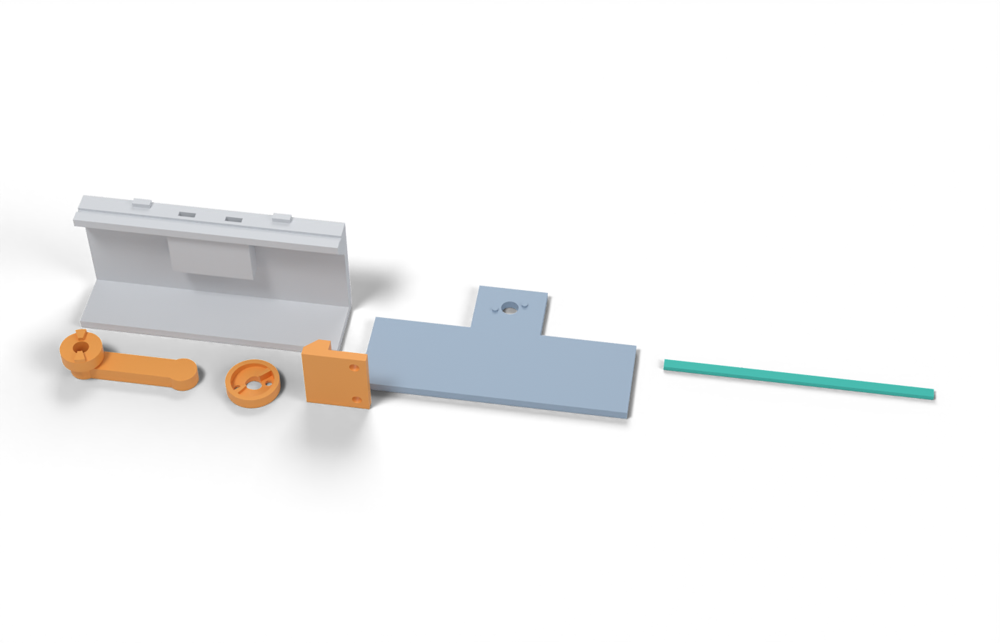
Print in ASA (TPU 85A for the seal), 0.2 mm layers, at least 4 walls; settings and the clearances used are in print/README.md. The parts are already turned the right way up for printing. The box and lid coupons are short test sections with this latch's box-side and lid-side features, so you can try the latch before building it into your own enclosure.
| File | Material | Qty | Size (mm) | How to print |
|---|---|---|---|---|
| handle.stl | ASA | 1 | 46 × 14 × 12 | Upside down, no supports. Press an M5 nut into the hex pocket; a second nut on top jams it to the stud. The two lugs underneath ride the ramp cup. |
| ramp-cup.stl | ASA | 1 | 18 × 18 × 4 | Upright, no supports. Two 1.5 mm ramps over 90 degrees, a 30-degree flat dwell and a stop; the handle closes clockwise. The two holes drop over the pegs on the lid tab. |
| keeper.stl | ASA | 1 | 21.2 × 7 × 24 | On its end, no supports, so the lip bends along the layers. 2 × M3 × 10 into the box. |
| box-coupon.stl | ASA | 1 | 90 × 24 × 41.6 | Upright, no supports. A section of box wall with this latch's box-side features: seal groove, hard stops, and an inside pillar with nut channels. Push an M3 square nut down each of the 2 channels in the rim before fitting the screws. Copy these features into your own box. |
| lid-coupon.stl | ASA | 1 | 90 × 50 × 3.9 | Flat, top up. A section of lid with this latch's lid-side features. Copy them into your own lid. |
| seal-strip.stl | TPU 85A | 1 | 90 × 3.4 × 1.5 | TPU 85A, 100 % infill, lying on its side. Press it into the rim groove: it stands 2.4 mm proud and the latch squeezes it 0.8 mm, until the lid lands on the hard stops. |
All printed parts in their assembled positions, for CAD: vise-action-screw-cam.step.
How to assemble
This follows the print files and the parts list above. They are first prototypes, so do one test assembly, on the box and lid coupons, before printing a full set.
Tools: 2.5 and 4 mm hex keys, two 8 mm spanners (M5 nuts), a hacksaw and file for the pawl, a 5.5 mm drill, a feeler gauge and calipers.
1. Print and prepare
- Print
handle.stlupside down,ramp-cup.stlupright andkeeper.stlon its end, all in ASA, as they come. - Print the box with the two hard stops and the nut channels, and the lid with its tab, 6 mm hole and two small pegs, or the box and lid coupons to try it first.
- Cut the pawl from 2 mm stainless strip: 7.6 mm wide, 11.6 mm long, both ends rounded to a 3.8 mm radius, with a 5.5 mm hole 3.8 mm from one end. The rounded ends let it turn past the keeper plate.
- Check the lid on the bare box: it should rest on the TPU rib with about a 0.8 mm gap above the hard stops. If it already touches the stops, the rib is too low and won't seal.
2. Keeper
- Drop 2 M3 square nuts down their channels from the rim.
- Screw the keeper to the box with 2 M3 × 10 screws, lip outward, snug but not hard.
3. The stud and the handle
- On the M5 × 40 screw: put the pawl on against the head, then a nut, and tighten the nut hard. Head and nut clamp the pawl; this screw is the stud.
- Drop the ramp cup onto the lid tab, its two holes over the pegs.
- Push the stud up through the lid tab and the cup from below, so the pawl sits under the tab, and thread an M5 nut onto it above the cup.
The handle closes clockwise, seen from above. It turns about 105° from open to closed: each lug climbs a ramp 1.5 mm, then sits on a flat dwell against a stop. The handle drives the stud through the nut in its hex pocket, so you set the clamp with the handle closed.
4. Set the clamp
- Close the lid. Turn the stud from below with the hex key so the pawl points at the wall, under the keeper lip.
- Put the handle on in its closed position: lugs on the dwells against the stops, the nut in its hex pocket. Hold the stud still with the hex key.
- Lift the handle off and screw the nut down the stud by whole turns, keeping the pawl pointing at the wall, until the pawl just touches the underside of the lip with the handle back on the dwells.
- Now go on one flat at a time (60°, 0.13 mm): lift the handle off, turn the nut one flat, press the handle back down onto the dwells. About 6 flats (0.8 mm) pull the lid down onto the hard stops; one or two more add preload. Turning by whole flats keeps the pawl pointing at the wall whenever the handle is closed.
- Screw the second nut down onto the handle's nut and tighten them against each other, holding the stud with the hex key. The handle, nut and stud now turn as one.
- Open and close it. Opening (anticlockwise), the stud drops 1.5 mm and the pawl swings out from under the lip; closing, the pawl swings back under and the ramps pull the lid down.
- Check with the latch closed:
- The lugs sit on the flat dwells against the stops.
- The lid sits on the hard stops: a 0.05 mm feeler gauge won't go in.
- If the handle won't climb onto the dwells, there's too much preload: open the jam nut and back the nut off a flat. If the lid can still be rocked, add a flat.
5. Final checks
- Open and close it a few times. Open, the pawl must clear the keeper lip so the lid lifts off; closed, the handle should stay on the dwell when you tap the lid.
- Fit every latch the same way; the reference lid needs 7–14. Close them in a cross pattern.
- This latch has no spring, so after the first hot weeks the seal sets and the force drops. Check the lid can't be rocked, and take up any play a flat at a time.
How it works
A lift-and-turn or T-handle turns a steel stud. A helical ramp between the handle hub and the housing, or between the pawl and the keeper, converts about 90 degrees of rotation into 1-1.5 mm of axial draw. A pawl hooked behind the frame pulls the lid down onto the gasket. A screw or nut on the stud sets the grip range. The load path is steel stud, printed pawl or ramp, printed or steel keeper.
Mechanical advantage
Two stages. (1) Grip adjustment: M5 nut, pitch 0.8 mm, set once. (2) Ramp: mean radius 8 mm, rise 1.5 mm in 90 degrees, tan(alpha) = 1.5/12.57 = 0.119 (6.8 degrees). Frictionless MA = 50 mm lever / (8 mm x 0.119) = 52. With mu = 0.3 the real ratio is ~14:1 (21 N at 50 mm gives ~1.04 N*m, ~300 N). Self-locking requires mu > tan(alpha) = 0.119. Grease or a smooth surface can erode that margin, so add a detent.
What limits the force
The printed load path at the frame: the keeper, ledge or hook, and the pawl bending. With a steel keeper or insert-boss interface, the pawl bending and ramp bearing allow ~300-450 N. With a printed ledge loaded through layers (box printed upright), shear across layers limits it to ~150-300 N. A measured standing ASA hook broke at only 17 kg (167 N) at 23 C in the CNC Kitchen test, geometry not stated. The M5 stud and the lid insert are not limiting.
Analyst's calculation
Analyst's sustained estimate: 150–450 N, typical 300 N; peak 1000 N.
[Web search budget was exhausted this run. No printed test of this mechanism type was found. Commercial ratings are static and come from the brief; the RS and Southco PDFs returned raw binary, so I could not re-read them.]
- Assumed printed analogue within 70 x 35 x 30 mm: steel M5 A2 stud, 60 mm lift-and-turn handle with 50 mm effective radius, ramp pair at mean radius 8 mm with 1.5 mm rise over 90 degrees. Printed pawl 20 wide x 14 thick, carrying an M5 hole (5.3 mm). Span between keeper supports 15 mm. Ramp contact 2 x (6 x 10 mm) = 120 mm2. Printed keeper ledge, root section 15 x 15 mm = 225 mm2.
- Ramp torque: T = Fr_m(tan a + mu)/(1 - mutan a) = F x 8 mm x 0.435 = 3.48 mm x F. For 300 N this is 1.04 Nm, ~21 N at the 50 mm handle. With mu = 0.15 it is 0.66 N*m and 13 N, but the ramp then barely self-locks.
- Pawl bending, centre-loaded (F = 4sigmaZ/L). Net section modulus Z = (20-5.3) x 14^2 / 6 = 480 mm3. In-plane allowable 3-5 MPa divided by Kt 1.3 for the hole gives 2.3-3.8 MPa. F = 4 x 2.3 x 480/15 = 294 N and 4 x 3.8 x 480/15 = 486 N. A pawl 18 x 12 mm gives only ~190-310 N.
- Printed ledge shear across layers, 1.5V/A <= 2 MPa (the brief's across-layer allowable, applied to shear as my assumption): A >= 1.5 x 300/2 = 225 mm2 for 300 N, and ~112 mm2 for 150 N.
- Ramp bearing, load normal to layers: 120 mm2 x 5-8 MPa = 600-960 N. Not limiting.
- Result: sustained 150 (printed standing ledge, small section) / 300 (steel keeper or insert boss, 20 x 14 pawl) / 450 N (large pawl, steel keeper). Peak ~1.0 kN (range 700-1200): pawl net-section break at ~35 MPa/Kt 1.5 gives ~2.9 kN, but ledge interlaminar failure and the measured standing-hook weakness cap it lower.
- Commercial anchor (static, not sustained, zinc/aluminium bodies): Southco N4 600 N working, 1200 N ultimate, 300 N average compression force. E3 450 N adjustable grip. M1-20 460 N short cam. 62-series 220-1250 N. Southco rates N4 and M1 as NEMA 4 / IP65-66 only with their flange or cup gasket.
- Preload retention is stroke-controlled like a rigid joint. Loss ~0.9 x set = 33-48 % after 70 C hot sun (35-52 % set). With a wave spring or disc stack under the nut, loss falls to ~10-17 %, but that needs ~2.4 mm of travel. Make the ramp rise 2.5-3 mm in that case. The ramp angle is then 0.19, mu 0.3 gives ~0.52 x r_m torque, and the hand force rises by about 20 %.
- Cold: with fixed travel the force rises ~2x at -30 C (gasket modulus x2.2), so adjust the grip at mid-temperature.
Adversarial review
Independent recalculation. Ramp: rise 1.5 mm in 90 deg at r=8 mm gives arc 12.57 mm, tan(alpha)=0.1194, T = F8(0.1194+0.3)/(1-0.0358) = 3.48 mm x F, checked. With the second interface, 5.6 mm x F. Pawl section: net Z = (20-5.3) x 14^2 / 6 = 480 mm3, checked. Pawl at 2.3-3.8 MPa gives 294-486 N, checked. Pawl break at 35/1.5 MPa gives 2.9 kN, arithmetic right but not governing. Ramp bearing 120 mm2 x 5-8 MPa = 600-960 N, not limiting. Keeper ledge bending (b=15, t=12): 120 N at a=6 mm and 240 N at a=3 mm at 2 MPa across layers, so the printed standing ledge is the weak link. This matches CNC Kitchen's ASA standing hook of 17 kg against 57 kg lying (verified; hook geometry unspecified on the page). Commercial anchors verified by decoding the PDFs locally: Southco N4 (RS PDF, encrypted but readable: working 600 N, average ultimate 1200 N, average compression force 300 N from a hand-turned T-handle), M1 (stainless, 1010 N short cam / 350 N long cam, IP66 with flange gasket), 62-series (1250 N). Southco E3 (GlobalSpec) returned 403 and could not be checked. No printed test of this mechanism was found, so all numbers are estimates. Fit to the requirement: at 200 N it needs 14 latches for 2.8 kN, so a 70 mm latch body does not fit around a 200 x 150 lid at the high gasket load; at the low 1.4 kN it needs 7 latches.
Issues raised:
- Sustained 300 N typical is 50 % above my figure. The pawl bending check is right (Z = 480 mm3; F = 4sigmaZ/L gives 294 N at 2.3 MPa and 486 N at 3.8 MPa), but the keeper side is not. The shear check for the printed ledge (1.5V/A at 2 MPa, 225 mm2 gives 300 N) ignores root bending. A hook loaded up through the layers sees sigma = 6Fa/(b*t^2) across layers. For b=15, t=12, a=3-6 mm and 2 MPa allowable that is 120-240 N. The 'steel keeper' alternative still has to be anchored in the printed box (lug or insert boss), which is limited to the same ~150-300 N as the screw boss. Typical 200 N.
- The hand-force estimate is optimistic. T = 3.48 mm x F counts only the ramp (checked: tan(alpha)=0.119, 6.8 deg, MA 52 frictionless, ~14:1 at mu=0.3). Under tension, a rotating stud needs a second sliding interface (hub on lid, or pawl on keeper) at ~7 mm radius with mu ~0.3, which adds ~2 mm x F. Total ~5.6 mm x F gives about 22 N at 200 N (34 N at 300 N) on a 50 mm lever instead of 14-21 N. Still inside the 20-50 N band, but with less margin. A Southco N4 ('average compression force 300 N, T-handle turned by hand', verified) shows that figure is reachable by hand with a good ramp.
- Peak 1000 N is too high for a printed latch. Commercial anchors are the verified Southco N4 (600 N working / 1200 N ultimate, zinc), Southco M1 in 316 stainless (350 N long cam / 1010 N short cam max static, NEMA 4/IP66 only with the supplied flange gasket) and Southco 62-series (1250 N max static). A printed ASA latch should not claim 83 % of a zinc latch's ultimate. A printed standing ledge breaks at about 540-1080 N (across-layer ~9 MPa from the 29 % rule). Peak 700 N (range 500-1000).
- Fixed-travel force scatter. Stack-up of +/-0.2 mm against a 0.48 mm squeeze gives roughly +/-40 % force, and the nut-set grip has to be redone after the first hot day. Rigid hot loss is 33-74 % (Texin 80 % set not used by the analyst), and printed ramp creep adds to it. Seal 6.
- Printed helical ramps and a handle, with grease, ice or dirt on the ramp, are the likely field failures. mu can drop below tan(alpha) = 0.12 and back-drive under vibration. Durability 6, usability 6 (lift, turn and a one-time grip adjustment per latch).
- The 'steel pawl/keeper' tiers need cut stainless plate. That is not common hardware in the user's sense, so the 300-450 N tiers do not describe 'printable with common hardware'.
Preload retention outdoors
Fair to poor if stroke-controlled: ~33-48 % loss after hot sun, from the 85A set (35-52 %) plus ramp and pawl creep. Better with a spring: add a wave spring or Belleville stack on the stud and lengthen the ramp rise to 2.5-3 mm, which cuts the loss to ~10-17 %. Adjustable by the stud nut, so it can be re-set after the first hot cycle. Printed ramps creep and wear (printed helical ramps are a known weak point).
Materials
ASA for the handle, housing, ramps and pawl. A steel (2 mm 304 stainless plate) pawl and keeper lifts the sustained limit above the printed value. UV-stabilised PC gives ~1.3-1.5x margin on printed parts (own judgement). Avoid PETG and PETG-CF at 60-70 C, and PA6-CF outdoors.
Hardware notes from the research
Flagged: not printed. A2/A4 stainless M5 stud or shoulder screw with jam nut, hardened washers, optional 304 stainless pawl and keeper plate, optional stainless wave spring or disc stack, optional brass bushing at the housing. Or buy the commercial Southco-type latch.
Design guidelines
- Print the pawl lying flat so bending stress runs along layers (XY plane). The stud hole axis is along Z. Minimum pawl 20 x 14 mm in section with a 5.3 mm hole. Use 4+ perimeters and 0.2 mm layers or finer.
- Frame-side keeper: use a steel keeper, or hook onto a steel pin or a screwed insert boss (the measured insert interface gives 119 kg in Z). If it must be a printed ledge, make it at least 15 x 15 mm at the root, 12+ mm thick, with a root fillet >= 3 mm. Do not rely on a thin standing hook: 17 kg in the CNC Kitchen test.
- Ramp: rise 1.5 mm in 90 degrees for a rigid stud (or 2.5-3 mm if you add a spring stack), mean radius 8-10 mm, contact area >= 120 mm2, faces printed flat so the load is normal to layers. End the ramp in a flat dwell of about 15 degrees plus a 0.3 mm detent so the handle cannot back-drive under vibration and creep.
- Lever and hub: 50 mm effective radius. Keep the hand force at or below 25 N at the typical load. Make the handle hub captive on the stud with a hex pocket or D-flat.
- Grip adjustment: M5 jam nut on the stud and a feeler-gauge or force-gauge set-up at assembly. Add a printed land stop at 0.75-0.8x the free bead height beside each latch.
- Pawl slot in the frame flange: ~22 x 15 mm for the 20 x 14 pawl. Check the flange does not lose too much area.
- Seal the stud hole in the lid with an O-ring or boot. Put the latch where rim stiffness allows (pitch ~28 mm on a flat 3 mm edge, ~110 mm with a 20 mm skirt).
- Internal corners: R >= 1.5 mm everywhere because ASA is brittle at -30 C.
Failure modes
- The printed keeper or ledge shears across layers under sustained hot load.
- The pawl cracks at the stud hole in bending.
- Ramp wear or creep gives progressive loss of draw.
- The ramp back-drives under vibration if mu falls below tan(alpha), for example with grease or ice.
- Gasket set and plastic creep take 33-48 % of a fixed-travel preload.
- The latch is closed 'off the ramp' and the force depends on where the handle parked.
- The stud hole leaks.
- Cold: force doubles at -30 C and a printed handle can crack.
Existing designs and commercial references
- Southco N4 compression latch datasheet (RS) [COMMERCIAL, not printable] — 600 N working, 1200 N ultimate, 300 N compression force (from brief). The PDF returned raw binary so I could not re-check the numbers.
- Southco M1 compression latch literature [COMMERCIAL, not printable] — NEMA 4 / IP66 with flange gasket (from brief). Not re-checked: PDF unreadable via fetch.
- Southco E3 compression latch (GlobalSpec) [COMMERCIAL, not printable] — 450/300 N static (from brief). My fetch returned HTTP 403.
- Southco 62-series datasheet [COMMERCIAL, not printable] — 220-1250 N static loads (from brief). Not re-checked.
Evidence gathered in the sweep
SUSTAINED (own est., printed analogue): 200-500 N; PEAK ~700-1200 N. COMMERCIAL (static, not sustained): Southco N4 600 N max working load, 1200 N average ultimate, 300 N average compression force on the frame https://docs.rs-online.com/eca8/0900766b801e0b3a.pdf ; E3 large 450 N adjustable grip / 300 N fixed grip (stainless 600/450 N) https://datasheets.globalspec.com/ds/southco/e3-16-206/829690b1-1f4e-4eab-b06d-1ffb2d2929cb ; M1-20 460 N short cam / 350 N long cam, M1-25 1010 / 350 N, NEMA 4/IP66 with flange gasket https://media.southco.com/media/static/Literature/m1-c.en.pdf ; 62 series 220 N small, 440-670 N medium, 1250 N large flush https://static.datasheets.com/doc/8464620-southco-62-10-23-rs-ds.pdf . Insert not limiting: M3 in PETG 1.17 kN https://www.cnckitchen.com/blog/helicoils-threaded-insets-and-embedded-nuts-in-3d-prints-strength-amp-strength-assessment . Most of these ratings come from search-result text. CONFIDENCE: medium for commercial numbers, low for the printed analogue.
Sources
- Southco N4 datasheet (RS) — From brief via search text; fetch unreadable.
- Southco M1 literature — From brief via search text; fetch unreadable.
- CNC Kitchen: comparing PLA, PETG and ASA (Prusament) — Verified by fetch. ASA hook lying 57 kg vs standing 17 kg (29 %). Used for the printed-ledge anchor.
- CNC Kitchen: helicoils, threaded inserts and embedded nuts (PETG M3) — Verified by fetch. Insert in Z pull-out 119 kg.
- Texin 985 datasheet — From brief, not re-fetched. Compression set and cold modulus.
- Ultrafuse TPU 85A TDS — From brief, not re-checked. Printed TPU set 26 % at 23 C, 52 % at 70 C.
Sources the reviewer flagged (dead, blocked or misdescribed):
- https://datasheets.globalspec.com/ds/southco/e3-16-206/829690b1-1f4e-4eab-b06d-1ffb2d2929cb : HTTP 403, 450/300 N E3 claim unverified
- https://docs.rs-online.com/eca8/0900766b801e0b3a.pdf : OK once decrypted locally (600 N working, 1200 N ultimate, 300 N compression force); the WebFetch tool alone cannot read it
- https://media.southco.com/media/static/Literature/m1-c.en.pdf : the 'NEMA 4/IP66 with gasket' claim is right; static loads are 1010 N (short cam) and 350 N (long cam), which the analyst did not use
- https://static.datasheets.com/doc/8464620-southco-62-10-23-rs-ds.pdf : 1250 N is the maximum static load of the part on the page; the '220-1250 N' range is not on that single page
- https://www.cnckitchen.com/blog/comparing-pla-petg-amp-asa-feat-prusament : hook numbers correct (PLA 73/40, PETG 55/25, ASA 57/17 kg), hook geometry not stated