No. 15 of 20 · Rectangular lids
Double-throw (case) latch
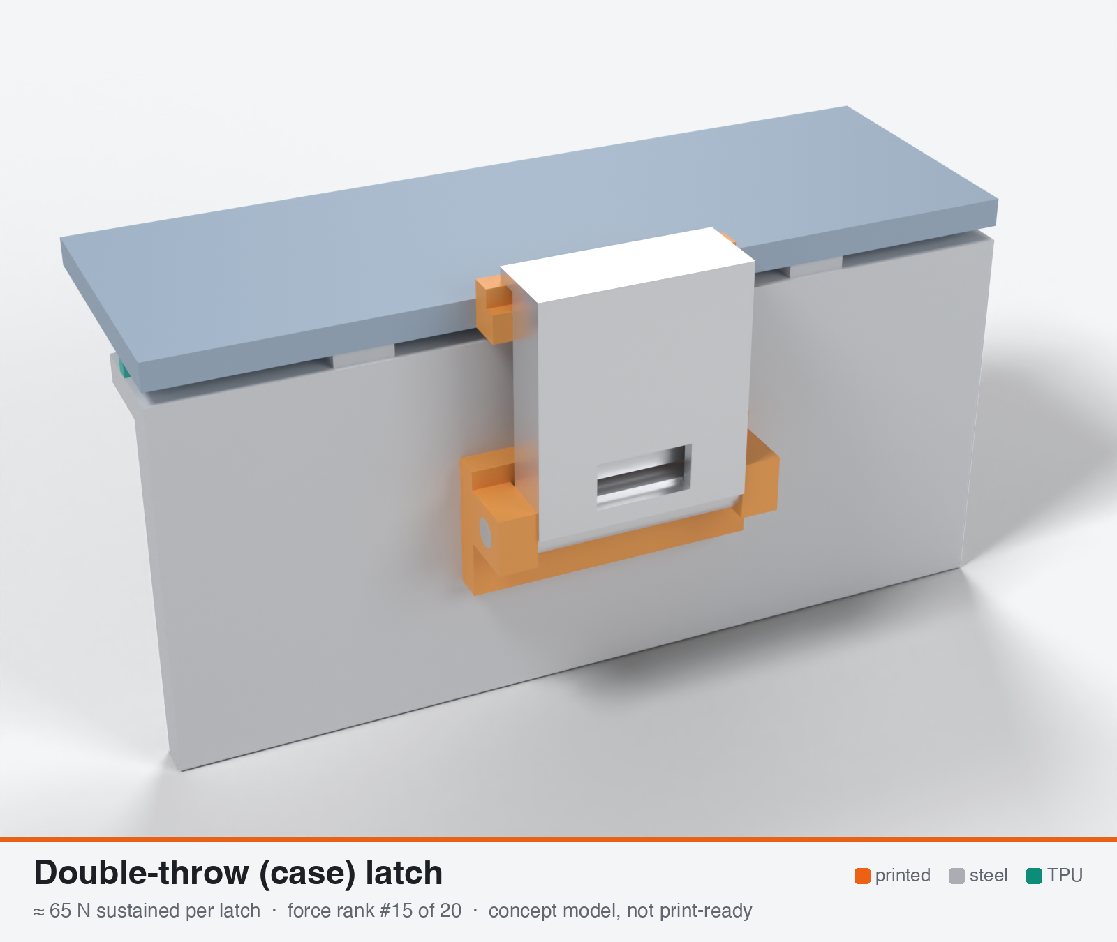
Double-throw / butterfly recessed case latch (stamped steel)
- Force rank
- 15 of 20
- Latches for the reference lid
- 22–44
- Build
- Mostly hardware
- Hand force to close
- ≈ 30 N
- Adjustable preload
- no
- Positive compression stop
- no
- Force basis
- calculated
- Review verdict
- corrected
- Confidence
- low
Verdict: The printed hook arm with 1 mm of load eccentricity holds about 45-76 N. The 90 kg figure belongs to a stamped steel latch and is not a gasket force. No stop or adjustment, and closing force depends on the finger. Cut from 85 N.
On this page
- Parts
- Print files
- How it works
- Mechanical advantage
- What limits the force
- Analyst's calculation
- Adversarial review
- Calibration adjustments
- Preload retention outdoors
- Materials
- Hardware notes from the research
- Design guidelines
- Failure modes
- Existing designs and commercial references
- Evidence gathered in the sweep
- Sources
Parts
Per latch: 1 part to print, 4 items to buy, 3 features printed into the box or lid and the TPU 85A seal. Parts marked † are not drawn in the 3D model. In the 3D gallery you can click a part to see where it sits. The last column links the print file, or an example of the part in a shop (see the shopping list).
| Part | Qty | Type | What to use | File or shop |
|---|---|---|---|---|
| Hinge bracket | 1 | ASA, flat on its back; match the ear gap and bore to the latch you buy | hinge-bracket.stl | |
| Butterfly latch | 1 | Buy | Stamped A2/A4 stainless latch (outer plate and inner lever), about 22 mm wide | Amazon.de |
| Hinge pin | 1 | Buy | 3 mm steel pin, 31 mm long | Grobotronics |
| Bracket screws † | 2 | Buy | M3 × 10 A2/A4 socket screws (DIN 912) | Grobotronics |
| Square nuts † | 2 | Buy | M3 square nuts (DIN 562), dropped down the channels in the box wall | Grobotronics |
| Keeper lip | 1 | Printed with the lid | Lip on the lid edge; an M4 stainless screw makes it adjustable | lid-coupon.stl |
| Hard stops | 2 | Printed with the box | Pads on the rim either side of the latch, 1.6 mm tall: 0.8 mm below the free seal | box-coupon.stl |
| Nut channels | 2 | Printed with the box | Inside pillar with a 5.7 × 2.0 mm channel per nut, open on the rim outside the seal; blind 3.4 mm screw holes, so no path into the box | box-coupon.stl |
| Seal strip | 1 | Seal (TPU 85A) | TPU 85A, 1.5 × 3.4 mm, in a 1.8 × 1.0 mm groove in the rim; the latch squeezes it 0.8 mm | seal-strip.stl |
Print files
Download all print files for this latch (ZIP, 56 kB)
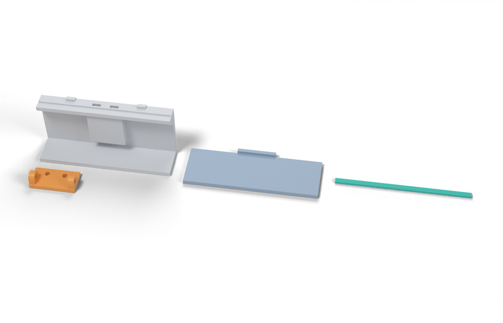
Print in ASA (TPU 85A for the seal), 0.2 mm layers, at least 4 walls; settings and the clearances used are in print/README.md. The parts are already turned the right way up for printing. The box and lid coupons are short test sections with this latch's box-side and lid-side features, so you can try the latch before building it into your own enclosure.
| File | Material | Qty | Size (mm) | How to print |
|---|---|---|---|---|
| hinge-bracket.stl | ASA | 1 | 30.6 × 16 × 10.2 | Flat on its back, no supports. Sized for a latch 22 mm wide on a 3 mm pin; match the ear gap and bore to the latch you buy. 2 × M3 × 10 into the box. |
| box-coupon.stl | ASA | 1 | 90 × 24 × 41.6 | Upright, no supports. A section of box wall with this latch's box-side features: seal groove, hard stops, and an inside pillar with nut channels. Push an M3 square nut down each of the 2 channels in the rim before fitting the screws. Copy these features into your own box. |
| lid-coupon.stl | ASA | 1 | 90 × 34 × 5 | Flat, top up. A section of lid with this latch's lid-side features. Copy them into your own lid. |
| seal-strip.stl | TPU 85A | 1 | 90 × 3.4 × 1.5 | TPU 85A, 100 % infill, lying on its side. Press it into the rim groove: it stands 2.4 mm proud and the latch squeezes it 0.8 mm, until the lid lands on the hard stops. |
All printed parts in their assembled positions, for CAD: double-throw-butterfly.step.
How it works
The Penn Elcom page calls this a recessed butterfly latch. The usual flight-case construction is a recessed dish with a spring-loaded folding or twist butterfly handle that engages a catch plate or keeper. The 'double-throw' label is the researchers', and neither the page nor my fetch confirms it. I analyse the printable principle as a quarter-turn cam draw, where a ramped cam or hook on the butterfly pulls the keeper down about 1.5 mm. A folding-lever over-centre reading has similar force limits. Commercial versions are 1.2 mm stamped steel with a steel spring, built for lid weight and shock, not gasket compression.
Mechanical advantage
Butterfly wing arm 18 mm / cam radius 8 mm = 2.25:1. The cam rises 1.5 mm per quarter turn (6 mm per revolution, lead angle 6.8 deg). With mu 0.3 the wedge factor is (1 - mu tan lam)/(tan lam + mu) = 2.3, so F_axial is about 5.2 x the finger force (155 N from 30 N). It is self-locking, since the 6.8 deg lead angle is below the 16.7 deg friction angle.
What limits the force
First hand torque (~0.5 N.m of finger effort gives ~155 N), then tension creep in the thin printed hook arm (a 10x5 mm arm at 3-5 MPa and Kt 1.5 holds ~100-170 N). The latch has a fixed geometry with little or no adjustment and no hard stop, so the gasket squeeze depends on tolerances. The commercial 90 kg rating (~883 N) is a lid-holding working load for a 1.2 mm steel latch and not a gasket draw force, and a printed copy will not match it.
Analyst's calculation
Analyst's sustained estimate: 70–200 N, typical 120 N; peak 400 N.
Commercial anchor (verified by re-fetch): Penn Elcom medium MOL recessed butterfly latch L905/928PBZ, max working load 90 kg (~883 N), 1.2 mm steel, zinc finish, 105x102 mm, 13 mm dish. The page does not say twist or double-throw. Printed version, own calc. Finger force 30 N at 18 mm arm = 0.54 N.m. Cam radius 8 mm, 6 mm lead per revolution (lead angle 6.8 deg), mu = 0.3 for printed-on-steel. F_axial = F_hand x (18/8) x 2.3 = 5.2 F_hand = 155 N (103 N at 20 N finger force, 207 N at 40 N). Hook arm tension: 10x5 mm = 50 mm^2, sustained 3 / 4 / 5 MPa, Kt = 1.5 gives 100 / 133 / 167 N. A thinner 36 mm^2 arm at 4 MPa gives 96 N. With the lead's conservative bearing and hot-sun margin I set low 70 N, typical 120 N, high 200 N. Peak: 80 N finger force x 5.2 = 414 N, and wing bending at 80 N x 18 mm over a 12x5 mm section is ~29 MPa, near the ASA limit, so peak ~400 N. On the reference lid at 100 mm pitch, 120 N is 1.2 N/mm, below the 2-4 N/mm window, and 250 mm pitch would be needed to hit ~0.5 N/mm. Series stiffness: hook arm EA/L = 1800 x 50/25 = 3,600 N/mm against ~625 N/mm gasket stiffness per latch at 100 mm pitch (own calc, 6.25 N/mm^2 x 100 mm). Loss = 0.85 x set, i.e. 25-49 % force loss for a 30-58 % compression set. Evidence note: the WebSearch budget was exhausted in this run, so no printed-butterfly test data was found.
Adversarial review
Independent recalculation: lead angle = atan(6 / (2 pi 8)) = 6.81 deg; wedge (1 - mu tan l)/(tan l + mu) = 2.299 at mu 0.3; efficiency tan l x wedge = 0.274; gain 2.25 x 2.299 = 5.17. F = 103 / 155 / 207 N at 20 / 30 / 40 N finger force, 414 N at 80 N. Including 4 mm pin friction (mu 0.3) the closing force at 30 N is 132 N. Hook arm 10x5 mm: factor 1 + 6e/t = 1 / 2.2 / 3.4 at e = 0 / 1 / 2 mm. Capacity at 4 MPa with Kt 1.5 is 133 / 61 / 39 N. Series fraction 3600/(3600+625) = 0.852, so loss is 0.85 x 30-58 % = 25-49 %. Sustained is therefore about 66-116 N from the closing force and about 60-90 N from the arm at e of about 1 mm. Typical 85 N is 29 % below the analyst's 120 N. I used 'corrected' because the arm capacity ignores eccentricity and the model is not the cited product. Fetched and confirmed: Penn Elcom (90 kg working load, 1.2 mm steel, zinc, 105x102 mm, 13 mm dish, no 'twist' or 'double-throw' wording); Lee Spring (music wire strength drops above about 121 C, rusts when wet; stainless superior outdoors); CNC Kitchen hook test; CNC Kitchen PC Blend review not re-fetched by me. The Albany fastener guide PDF text could not be extracted by my fetch, so the salt-spray hours (12-72 h, 96-120 h) are unverified by me. The WebSearch budget was exhausted, so I could not look for the real meaning of 'double-throw' or for printed butterfly or cam latch tests.
Issues raised:
- The mechanism identity is unverified. The Penn Elcom page (re-fetched) calls it a 'Recessed Butterfly Latch' and gives 1.2 mm steel, zinc finish, 105x102 mm, 13 mm dish, 231 g, 10 holes, and 'Maximum working load capacity: 90kg'. It does not say twist, cam or double-throw. The 'double-throw' label and the quarter-turn cam are the analyst's own model of a hypothetical printed latch. The 90 kg (883 N) figure is a lid-holding rating for a steel latch, correctly not used as a draw force.
- The wedge arithmetic reproduces: lead 6 mm/rev on r = 8 mm gives a 6.8 deg lead angle, wedge factor 2.30, gain 18/8 x 2.30 = 5.17, so 155 N from a 30 N finger. It ignores pivot friction. With a 4 mm pin at mu 0.3 the closing force is about 132 N. A pure cam is only about 27 % efficient.
- Hook-arm capacity is inconsistent with the snap-fit analysis. The 100 / 133 / 167 N figure for the 10x5 arm at 3 / 4 / 5 MPa and Kt 1.5 assumes zero eccentricity (e = 0). With the hook line offset e = 1 mm the arm holds 45 / 61 / 76 N (68 / 91 / 114 N without Kt). With e = 2 mm it holds 29-49 N. The arm therefore limits sustained force to about 60-90 N, below the 120 N typical.
- The latch is force-limited by the user's twist, not stroke-limited. At 132-155 N through the series stiffness (hook 3600 N/mm in series with 625 N/mm of gasket per 100 mm pitch) the gasket compresses only about 0.25-0.29 mm. The 1.5 mm cam throw is mostly consumed by FDM clearance. Clamp force therefore varies about +/-35 % with 20-40 N finger effort (103-207 N), and there is no stop or adjustment.
- Sustained = closing force x (1 - set loss). With 25-49 % loss (ks/(kg+ks) = 0.85) a 132-155 N closing force falls to 67-116 N. At 100 mm pitch this is 0.5-1.0 N/mm, below the 2 N/mm floor. Typical lowered from 120 to 85 N.
- Peak. 80 N finger x 18 mm x 2.3 gives 414 N. With pivot friction it is 350 N, and wing bending (12x5 mm) is 28.8 MPa, consistent. Peak set to 350 N.
- Outdoor durability. A zinc-plated stamped steel latch only has 12-72 h salt-spray class (yellow zinc 96-120 h) per the analyst's Albany source, which I could not read. A printed cam under 100 N at 60 C will creep and wear, with back-out in vibration unless a detent holds it. The recess collects water. Durability 5 reduced to 4. Usability 8 reduced to 7 because the twist effort sets the preload.
Calibration adjustments
- sustained_N.typical: 85 (reviewer; range 45-150) → 65 (range 40-120). The reviewer deducted gasket set loss from a hand-limited closer, which the cap, bayonet and multi-point reviews did not do, so that deduction was inconsistent. The structural limit is the 10x5 mm hook arm with 1 mm of eccentricity (45-76 N at 3-5 MPa with Kt 1.5), the same hook-arm limit as the cam-hook (55 N) and bail (50 N). Typical set to the arm limit.
Preload retention outdoors
Poor. The printed hook arm is stiff (3,600 N/mm vs ~625 N/mm gasket per latch), so ~85 % of the gasket compression set at 70 C (30-58 %) appears as force loss, 25-49 %. The geometry is fixed, so there is no way to retension unless the keeper is a screw. The cam is self-locking at rest, but vibration and thermal cycling plus creep of the contact surfaces can back it off.
Materials
Buy the stamped latch in stainless for outdoor use. Zinc-plated steel only gives 12-72 h salt spray and yellow zinc 96-120 h (albanycountyfasteners, from the lead). For printed parts use ASA for the wings, cam and recess, with a stainless pin and keeper. PC (UV-stabilised) for more creep margin. Not PETG at 60-70 C.
Hardware notes from the research
Stamped stainless (A2/A4) butterfly latch and keeper (buy), or for a printed copy a 4 mm stainless pin, stainless keeper screw or bar and a stainless spring.
Design guidelines
- Use it as a secondary keeper or alignment aid beside a proper clamp. Do not use it as the primary clamp for a solid 85A TPU gasket.
- If printing a twist-cam version: cam radius ~8 mm, 6 mm per revolution lead (6-8 deg lead angle so it self-locks), quarter-turn stop, wing span 36-45 mm, hook arm >= 10x5 mm printed flat with the load in XY.
- Make the keeper an adjustable M4 stainless screw or bar so preload can be retensioned. Add a printed hard stop beside the latch at 0.75-0.8x the free bead height.
- Use a 4 mm stainless pin with bearing <= 8 MPa (4x8 mm = 32 mm^2 is good for ~250 N sustained). Pin axis along Z.
- Add a detent or spring so the butterfly cannot back out in vibration. Keep the recess drained.
- Fillets >= 1.5 mm on the hook and cam root. ASA has only ~3 kJ/m2 notched Charpy at -30 C.
- Place latches at the rim-bending pitch limit (~28 mm for a 3 mm flat lid edge, ~110 mm with a 20 mm skirt). Several latches of ~120 N are what the lid needs.
Failure modes
- Hook arm creep or fracture at 60-70 C
- Cam or wing wear and slip under vibration, so the latch backs out
- Wing breakage when over-torqued by hand (peak ~400 N)
- Gasket compression set loses 25-49 % of the force with no way to retension
- Zinc-plated steel corroding outdoors (96-120 h salt-spray class)
- Recess collecting water and debris
- FDM tolerance giving too little or too much squeeze
Existing designs and commercial references
- Penn Elcom medium MOL recessed butterfly latch L905/928PBZ (commercial steel reference, not printable) — Verified: 90 kg max working load, 1.2 mm steel, zinc, 105x102 mm, padlockable. Page does not say twist or double-throw.
Evidence gathered in the sweep
COMMERCIAL: Penn Elcom medium MOL recessed butterfly latch L905 series, 90 kg (~880 N) maximum working load, 1.2 mm steel, zinc finish, verified by me https://translations.penn-elcom.com/medium-mol-recessed-latch-with-padlock-bracket-in-deep-dish-l905-928pbz . No printed estimate; the sustained force of a printed copy was not estimated and is expected to be low. CONFIDENCE: low.
Sources
- Penn Elcom medium MOL recessed latch L905/928PBZ — Verified by re-fetch: 90 kg working load, 1.2 mm steel, zinc finish, 10.5x10.2 cm, 13 mm dish, 231 g, listed as a butterfly latch with no double-throw wording.
- Lee Spring: music wire versus stainless steel — Verified: music wire rusts and tops out ~121 C; 302/304 stainless to ~288-316 C. Use stainless springs outdoors.
- Albany County Fasteners: fastener materials and coatings guide — From the lead (zinc plate 12-72 h and yellow zinc 96-120 h salt spray); not re-fetched.
- CNC Kitchen: comparing PLA, PETG and ASA — Verified: standing vs lying hook strength (ASA 17 vs 57 kg); ASA softens 110 C.
- CNC Kitchen: Prusament PC Blend review — Verified: PC Blend hooks 74 and 77 kg lying vs 22-35 kg standing, softens ~110 C, fails 125 C; no creep data.
- filamentspecs: creep resistance of 3D printed parts — Verified: PETG joint lost ~11.5 % preload in 7 days vs ~3 % PLA.
Sources the reviewer flagged (dead, blocked or misdescribed):
- https://translations.penn-elcom.com/medium-mol-recessed-latch-with-padlock-bracket-in-deep-dish-l905-928pbz is quoted correctly (90 kg working load, 1.2 mm steel, zinc) but never says 'double-throw' or twist. The 'double-throw' naming is unsupported
- https://www.albanycountyfasteners.com/media/48/29/31/1764608481/fastener-materials-and-coatings-guide.pdf: the salt-spray hours (12-72 h zinc, 96-120 h yellow zinc) could not be read by my fetch and are unverified
- https://www.leespring.com/music-wire-versus-stainless-steel: the 121 C limit for music wire is right, but the 288-316 C figure is a general stainless range, not stated for 302/304, and '25-30 % weaker' is the analyst's derivation, not a page statement
- https://www.cnckitchen.com/blog/prusament-pc-blend-review was not re-fetched by me; the PC Blend hook numbers (74 / 77 kg lying, 22-35 kg standing) are unverified in this review