No. 11 of 20 · Rectangular lids
Multi-point rod latch
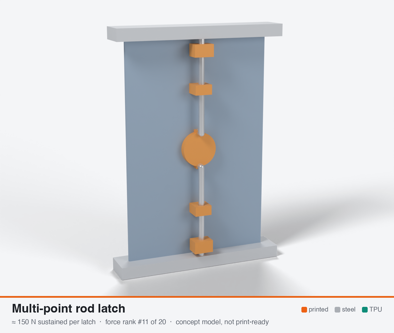
Multi-point rod latch (handle drives rods or bellcranks to top and bottom latch points)
- Force rank
- 11 of 20
- Latches for the reference lid
- 10–19
- Build
- Mostly hardware
- Hand force to close
- ≈ 50 N
- Adjustable preload
- yes
- Positive compression stop
- no
- Force basis
- estimated
- Review verdict
- corrected
- Confidence
- low
Verdict: This is per latch POINT on a 4-point door. One handle delivers only about 0.57-0.8 kN in total before set loss, which is 0.5-1.1 N/mm. It does not fit the envelope. Rod, bellcrank and guide complexity outdoors hurts durability.
On this page
Parts
Per door: 3 parts to print, 4 items to buy, 2 features printed into the box or lid and the TPU 85A seal. Parts marked † are not drawn in the 3D model. In the 3D gallery you can click a part to see where it sits. The last column links the print file, or an example of the part in a shop (see the shopping list).
| Part | Qty | Type | What to use | File or shop |
|---|---|---|---|---|
| Handle with shaft | 1 | ASA, grip face down; 80 mm lever, 10 mm shaft with a flat | handle.stl | |
| Hub cam | 1 | ASA, flat; two spiral slots move the rods 6 mm in a 90° turn | hub-cam.stl | |
| Latch points | 2 | ASA, on its side; 12° face that draws the door in 1.3 mm | latch-point.stl | |
| Rod guides | 2 | Printed with the lid | Blocks on the door's inner face with 5.4 mm holes | door-coupon.stl |
| Frame keepers | 2 | Printed with the box | Lug with a 12° face beside a 6 mm rod hole, in the frame | frame-coupon.stl |
| Rods | 2 | Buy | 5 mm steel rod, about 95 mm long, bent 90° with a 6 mm leg at the hub end | Grobotronics |
| Shaft O-ring † | 1 | Buy | O-ring 10 × 2 mm (in the NBR kit), in the counterbore round the shaft, outside the door | Grobotronics |
| Hub screw † | 1 | Buy | M3 × 8 socket screw with a washer, into a square nut in the shaft | M3 screw · washer · square nut |
| Clamp screws † | 2 | Buy | M3 × 8 socket screws into square nuts; clamp the latch points to the rods | M3 screw · square nut |
| Door gasket | 1 | Seal (TPU 85A) | TPU 85A rib round the door; design it into your door and frame |
Print files
Download all print files for this latch (ZIP, 0.2 MB)
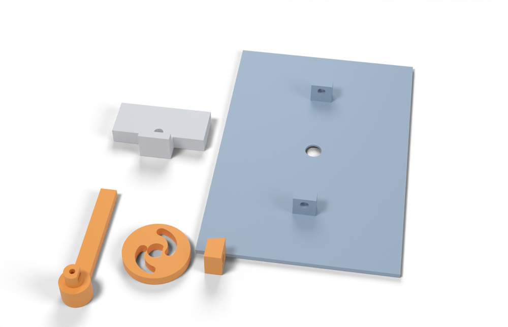
Print version: The hub drives the rods through two spiral slots (6 mm of travel in a quarter turn), and each rod end carries a latch point whose 12° face rides on a lug in the frame and draws the door in 1.3 mm.
Print in ASA (TPU 85A for the seal), 0.2 mm layers, at least 4 walls; settings and the clearances used are in print/README.md. The parts are already turned the right way up for printing. The box and lid coupons are short test sections with this latch's box-side and lid-side features, so you can try the latch before building it into your own enclosure.
| File | Material | Qty | Size (mm) | How to print |
|---|---|---|---|---|
| handle.stl | ASA | 1 | 18 × 84 × 22 | Grip face down, shaft up, no supports. The round part of the shaft turns in the door; a 10 × 2 mm O-ring in the door's counterbore seals it. Push an M3 square nut into the shaft's side slot before fitting the hub. |
| hub-cam.stl | ASA | 1 | 40 × 40 × 6 | Flat, no supports. The bent ends of the rods ride in the spiral slots. An M3 × 8 screw with a washer holds it on the shaft. |
| latch-point.stl | ASA | 2 | 10 × 15 × 16 | On its side, no supports. Fit one on each rod end (the lower one turned over), clamped with an M3 × 8 screw into a square nut. Its 12-degree face draws the door in 1.3 mm. |
| frame-coupon.stl | ASA | 2 | 60 × 36 × 18 | Lug up, no supports. A section of frame with the keeper lug and the rod hole; one at the top, one (turned over) at the bottom. |
| door-coupon.stl | ASA | 1 | 120 × 180 × 17 | Outer face down, no supports. 120 × 180 mm door with the two rod guides, the shaft hole and the O-ring counterbore. |
All printed parts in their assembled positions, for CAD: multi-point-rod-latch.step.
How it works
A handle turns a pinion, cam or crank. That drives two or more rods (or cables) in guides to latch points at the top, bottom and sometimes the sides of the door. Each point has a ramped hook or roller that pulls the door against a keeper, so one handle motion pulls the door at several places. The hand effort is shared between the rods. The closing force summed over all points is therefore set by the handle, not multiplied by the number of points. Printed parts would be housings, guides, bellcranks and keepers. The rods and pins should be steel.
Mechanical advantage
Handle 80 mm / pinion 8 mm = 10:1, efficiency 0.7, gives 7:1 to total rod force. A 15 deg rod ramp (mu 0.15-0.3) adds a wedge factor (1 - mu tan a)/(tan a + mu) = 1.6-2.3. Total handle-to-axial is ~11-16:1, shared by all points. A 4-point door gets half the per-point force of a 2-point door for the same handle effort.
What limits the force
Hand effort shared across points (~0.6-0.8 kN total on the door for 50 N at an 80 mm handle, whatever the number of points), then bearing stress under the steel pins in the printed bellcranks and guides (a 4 mm pin in 8 mm thickness = 32 mm^2 gives 256 N at 8 MPa). Hinge-side compression comes only from lid stiffness and hinge position. Does not fit the 70x35x30 mm latch envelope, since the rods and handle run the whole door span.
Analyst's calculation
Analyst's sustained estimate: 120–450 N, typical 250 N; peak 700 N.
Own first-principles estimate. No published rating or test for printed multi-point latches was found; the cited article gives no numbers. Assumed hand force 50 N on an 80 mm handle, pinion radius 8 mm, efficiency 0.7. Total rod force F_t = 50 x 80/8 x 0.7 = 350 N, split over 2 rods = 175 N each. Ramp 15 deg: axial per point = 175 x 1.62 (mu 0.3, printed ramp) = 283 N, or 175 x 2.30 (mu 0.15, steel on steel) = 402 N. Total on the door = 570-800 N. With 4 points the per-point force halves to ~140-200 N. Bearing check: 4 mm pin x 8 mm bellcrank = 32 mm^2, which at 5 / 8 / 10 MPa (the lead's sustained bearing rule ~8-10 MPa) gives 160 / 256 / 320 N. 5 mm pin x 10 mm = 50 mm^2 gives 250 / 400 / 500 N. Short-term bearing ~22 MPa on 32 mm^2 gives ~700 N (peak). Keeper ramp 12x6 mm = 72 mm^2: 300 N is 4.2 MPa (fine). A 4 mm stainless rod 60 mm unsupported has Euler load 6.6 kN (not limiting). Summary: low 120 N (4-point door, hot, 5 MPa), typical 250 N, high 450 N (5 mm pin, thicker lever). Compared with the reference lid: 4 points x 250 N = 1.0 kN, which is 36-71 % of the required 1.4-2.8 kN total. To reach 2.8 kN by hand the handle torque would need to be about 14 N.m (about 3.5x a normal handle), so this suits a gasket at the 1-2 N/mm end or a stiffer, larger handle. Stiffness: 4 mm steel rod 400 mm long has EA/L = 6,000 N/mm. Stiffness is then set by printed pins and ramps, so most of the gasket compression set shows up as force loss unless the linkage has adjusters or a spring. Evidence note: the WebSearch budget was exhausted in this run, so no more sources were collected; confidence is low.
Adversarial review
Independent recalculation: rod force = 50 N x 80 mm / 8 mm x 0.7 = 350 N. Wedge factor for a 15 deg ramp is (1 - mu tan a)/(tan a + mu) = 1.62 at mu 0.3 and 2.30 at mu 0.15, as the analyst says. Door total 567-804 N. Per point: 2-point 283-402 N, 4-point 142-201 N at closing. Bearing: 4x8 mm pin at 5 / 8 / 10 / 22 MPa gives 160 / 256 / 320 / 704 N, and 5x10 mm at 8 MPa gives 400 N. Needed handle torque for 2.8 kN is about 14 N.m at mu 0.15 and about 20 N.m at mu 0.3. My typical of 150 N per point is 40 % below the analyst's 250 N, outside the 30 % tolerance, so it is corrected. The per-point sustained force is hand-limited, not bearing-limited. Fetched and confirmed: Magazine Industry (qualitative only, no span or latch-count data); CNC Kitchen threaded-insert page (numbers as quoted; test temperature and orientation not stated); CNC Kitchen ASA/PETG hook test (standing hooks 29 % / 46 % of lying); filamentspecs (PETG 11.5 % vs PLA 3 % preload loss, no conditions). GlobalSpec returned 403 for the analyst and I did not re-check it. The whole mechanism rests on first-principles estimates with no printed reference, so confidence is low.
Issues raised:
- Internal inconsistency. The analyst's own chain gives a hand-limited TOTAL of 350 N rod force x 1.62 = 567 N (mu 0.3) or x 2.30 = 804 N (mu 0.15) on the whole door. The summary then states 'typical 250 N per point' and '4 points x 250 N = 1.0 kN'. One handle cannot deliver 1.0 kN. For a 4-point door the closing force per point is 142 N (mu 0.3) or 201 N (mu 0.15). For a 2-point door it is 283 / 402 N.
- Sustained force must also allow for gasket set. With a stiff rod and pin chain, 25-55 % is lost, which leaves 64-106 N per point (4-point, mu 0.3) or 128-213 N (2-point). A series spring that holds the loss to 10 % gives 128-181 N (4-point) or 255-362 N (2-point). The typical value drops from 250 N to 150 N, with 60 N for a hot stiff 4-point door and 300 N for a spring-compensated 2-point door, which is bearing-limited anyway.
- The door total of 0.25-0.8 kN is 0.35-1.15 N/mm on a 700 mm path, below the 2 N/mm floor of the design window. The analyst's 'handle would need about 14 N.m' used mu 0.15. At mu 0.3 the handle torque for 2.8 kN is about 20 N.m, roughly 5x a 4 N.m hand effort. Seal 5 is reduced to 4.
- The handle is itself a load path. A 12x5 mm printed handle bending section at 50 N x 80 mm sees 80 MPa, double the strength of ASA. It needs about 20x10 mm (12 MPa) or a steel handle. The brief's comfortable finger force is 20-50 N, so 50 N is the upper end. Printed levers and bellcranks must be designed for the 100 N overload case, which is where the 600-700 N peak per point comes from.
- Peak. Bearing under a 4 mm pin x 8 mm is 32 mm^2 x 22 MPa = 700 N at the instantaneous (not sustained) level. A hand overload of 100 N at mu 0.3 gives about 570 N per point for a 2-point door. Peak set at 600 N per point.
- Sources give no force data. The Magazine Industry page is purely qualitative (multi-point latching for large spans, compression latches for gaskets, no numbers). GlobalSpec is not verifiable. The CNC Kitchen insert data are M3 axial pull-out values (PETG: insert 119 kg, direct screw 118, side-pocket nut 86, bottom-pocket nut 166) from flat 4-perimeter 100 % infill coupons. The page does not state test temperature or orientation, and none of it is a bearing or sustained value. Existing_designs is empty, so there is no printed example. The force_basis 'estimated' is honest.
- Does not fit the 70x35x30 latch envelope; rods and handle span the door. Guides, rod ends, e-clips and keepers in outdoor ice and dust add many failure points, so outdoor durability 6 is reduced to 5 and usability 7 to 6.
Preload retention outdoors
Moderate with adjusters, weak without. Steel rods are very stiff (~6,000 N/mm), so the linkage cannot absorb gasket compression set. Printed bellcrank pin bores and ramps creep under 5-8 MPa bearing at 60 C. Expect roughly 25-55 % loss in the first hot season unless the keepers or rod-end clevises are adjustable and the handle cam over-centre includes a spring.
Materials
ASA for housings, guides and bellcranks, in thick solid sections. UV-stabilised PC if more creep margin is needed (probably 1.3-1.5x, the lead's judgement). Not PETG at 60-70 C. Steel parts: A2/A4 stainless rods, pins and keepers. PA6-CF is out outdoors.
Hardware notes from the research
A2/A4 stainless rods or flat bar (4-5 mm), M4/M5 stainless clevis rod ends, 4-5 mm stainless pins with e-clips, stainless keepers or rollers, a handle with cam or pinion, a spring or over-centre detent, and heat-set inserts for adjusters.
Design guidelines
- Keep the handle lever long (>= 80-100 mm) and the pinion small (6-8 mm), but design all printed load paths for a 100 N worst-case hand force and the peak ~700 N per point.
- Use steel pins >= 4-5 mm through printed levers at least 8-10 mm thick (bearing <= 8 MPa sustained). Put pin axes along Z and print the lever flat, so bearing loads run in XY.
- Make ramp keepers 12x6 mm or larger, ramp angle 12-15 deg, lubricated stainless or PTFE contact. Add a printed hard stop beside each point at 0.75-0.8x the free bead height.
- Place latch points so the pull is near the gasket and not out at the corners. On a hinged lid the hinge side is compressed only by lid stiffness, so add a hinge-side lug or stiffen the rim.
- Rod-end clevises or keeper screws at every point for adjustment. Include a spring in the handle linkage (about 4x softer than the gasket per point) to cut the loss from compression set to < 10 %.
- Guide the rods every 60 mm or less. Stainless rod unsupported 60 mm is fine against buckling, but printed guide bores need 0.3-0.4 mm clearance and 4+ perimeters.
- Do not use this on small lids. Per-point force is about the same as a single compression latch, so the benefit is only load spreading on large lids with a stiff rim.
- Seal the rod entry points with small gaskets or boots, because rods passing through the box wall are a leak path.
Failure modes
- Printed bellcrank or guide bore elongation (bearing creep) giving backlash and loss of pull-in
- Hinge side under-compressed, causing a leak at the hinge side
- Rod binding from FDM warp or misaligned guides
- Seized or corroded linkage (mixed metals)
- Handle effort too low to hit the gasket force, so the door only closes partway
- Uneven squeeze between points from different rod lengths or keeper wear
- Ramp wear and slip under vibration
Evidence gathered in the sweep
SUSTAINED per point: no published rating; same order as a single compression latch (several hundred N, per industrial researcher). No numbers found. Qualitative: multi-point latching recommended for large door spans https://www.magazine-industry-usa.com/news/1936-getting-the-latch-and-hinge-specification-right ; marketed for gasket-sealed outdoor use (search text) https://www.globalspec.com/ds/3851/areaspec/features_gasket . CONFIDENCE: very low.
Sources
- Magazine Industry USA: getting the latch and hinge specification right — Verified: only qualitative. Multi-point latching for large door spans, compression latches suit gasket sealing and vibration. No force, span or latch-count figures.
- GlobalSpec: gasket latches — From the lead. Re-fetch returned HTTP 403, so unverified.
- CNC Kitchen: helicoils, threaded inserts and embedded nuts strength — Verified: M3 in PETG pull-out averages 119 kg heat-set insert, 118 kg direct screw, 86 kg side-pocket nut, 166 kg bottom-pocket nut (room temperature, flat 4-perimeter 100 % infill coupons). Bearing in the printed lever, not the thread, is the limit.
- CNC Kitchen: comparing PLA, PETG and ASA — Verified: standing hooks only 29 % (ASA) of lying strength, so put lever and bearing loads in XY.
- filamentspecs: creep resistance of 3D printed parts — Verified: PETG bolted joint lost ~11.5 % preload in 7 days vs ~3 % PLA.
Sources the reviewer flagged (dead, blocked or misdescribed):
- https://www.globalspec.com/ds/3851/areaspec/features_gasket was reported 403 by the analyst and I did not re-check it. Treat as unverified
- https://www.magazine-industry-usa.com/news/1936-getting-the-latch-and-hinge-specification-right is real but purely qualitative. It supports only 'multi-point latching exists for large spans', not any force or latch-count figure
- https://www.cnckitchen.com/blog/helicoils-threaded-insets-and-embedded-nuts-in-3d-prints-strength-amp-strength-assessment: the numbers are right, but the analyst's 'room temperature' label is an assumption (the page states no test temperature), and the data are pull-out values that do not apply to a pin-bearing load path
- https://filamentspecs.com/creep-resistance-3d-printed-parts/ is quoted correctly (11.5 % vs 3 %) but has no bolt, stress or temperature conditions, so it cannot support the 25-55 % loss range