No. 10 of 20 · Rectangular lids
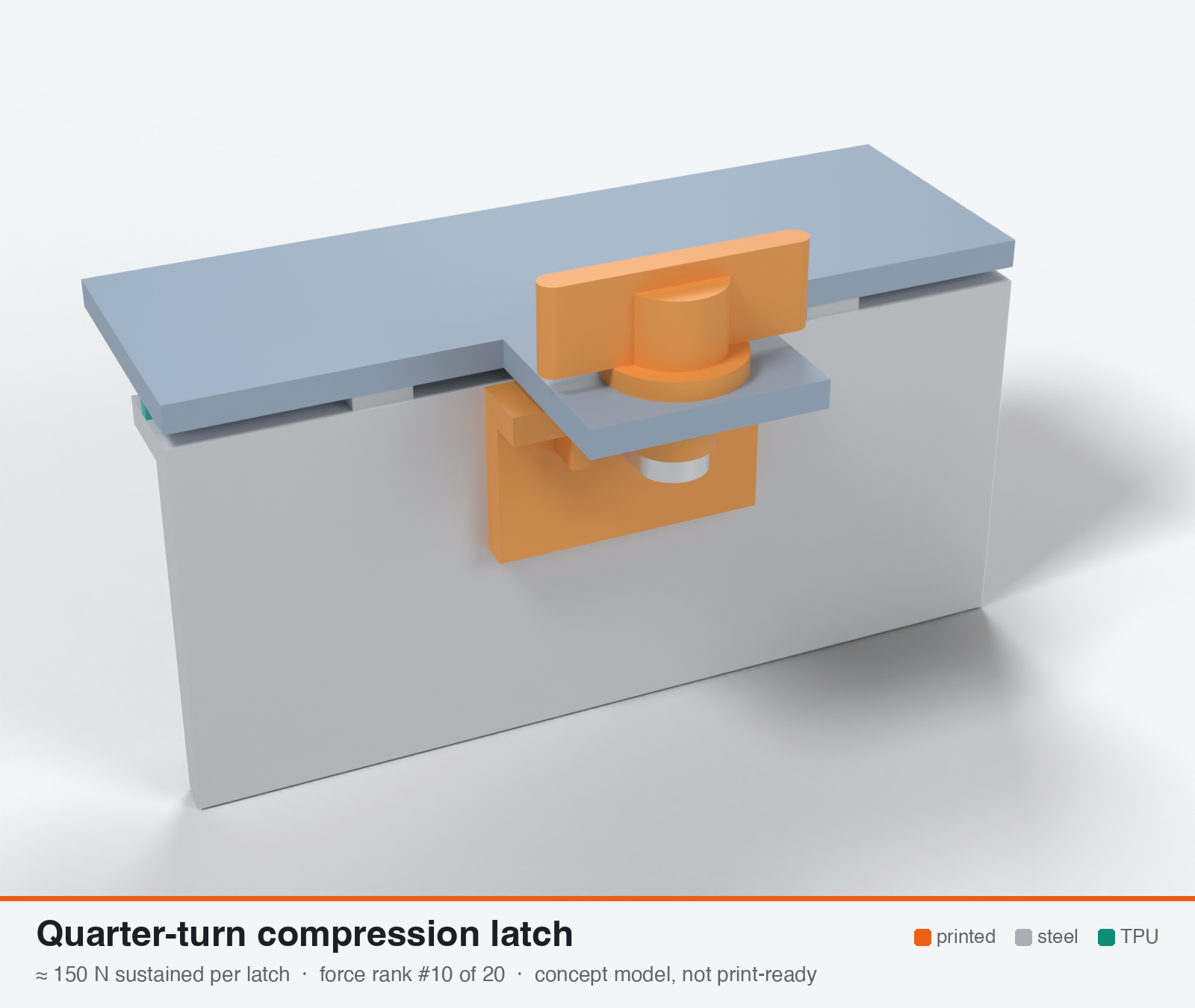
Quarter-turn compression latch
Quarter-turn compression latch (steel cam and ramp, 4-6 mm draw-down)
- Force rank
- 10 of 20
- Rank for outdoor sealing
- 10
- Latches for the reference lid
- 10–19
- Build
- Printed + steel hardware
- Hand force to close
- ≈ 33 N
- Adjustable preload
- yes
- Positive compression stop
- yes
- Force basis
- estimated
- Review verdict
- corrected
- Confidence
- low
Verdict: A printed pawl alone gives about 115 N. 150-350 N needs a steel pawl and a keeper. Commercial 4-6 mm ramp travel does not match the 0.5 mm gasket stroke, so force scatter is about 40 %. Better with foam or a thin rib than with the 85A design rib.
Why it ranks #10 for sealing: About 150 N (range 60-300) and only with a steel pawl and keeper, since a printed pawl holds about 115 N. Convenient and has a positive stop, but 4-6 mm commercial travel against a 0.5 mm gasket stroke gives about +/-40 % force scatter. Better suited to foam or a thin rib than the 85A design rib; included to fill the top 10, not as a recommendation.
On this page
Parts
Per latch: 3 parts to print, 5 items to buy, 3 features printed into the box or lid and the TPU 85A seal. Parts marked † are not drawn in the 3D model. In the 3D gallery you can click a part to see where it sits. The last column links the print file, or an example of the part in a shop (see the shopping list).
| Part | Qty | Type | What to use | File or shop |
|---|---|---|---|---|
| Housing | 1 | ASA, flange down; a bushing in the lid tab | housing.stl | |
| Wing knob | 1 | ASA, flat; hex pocket for an M5 nut | knob.stl | |
| Ramp keeper | 1 | ASA, on its end; the underside ramps down 1.5 mm to a flat dwell, with a stop block | ramp-keeper.stl | |
| Screw † | 1 | Buy | M5 × 40 A2/A4 socket screw (DIN 912), head under the pawl | Grobotronics |
| Pawl | 1 | Buy | 2 mm stainless plate, 7 × 12.3 mm with a rounded end and a 5.3 mm hole, cut by hand | Edelstahl-Lechner |
| Nuts † | 3 | Buy | M5 A2/A4 nuts: one clamps the pawl against the screw head, one sits in the knob's pocket and one jams it | Grobotronics |
| Keeper screws † | 2 | Buy | M3 × 10 A2/A4 socket screws (DIN 912) | Grobotronics |
| Square nuts † | 2 | Buy | M3 square nuts (DIN 562), dropped down the channels in the box wall | Grobotronics |
| Lid tab with hole | 1 | Printed with the lid | 8.4 mm hole for the housing | lid-coupon.stl |
| Hard stops | 2 | Printed with the box | Pads on the rim either side of the latch, 1.6 mm tall: 0.8 mm below the free seal | box-coupon.stl |
| Nut channels | 2 | Printed with the box | Inside pillar with a 5.7 × 2.0 mm channel per nut, open on the rim outside the seal; blind 3.4 mm screw holes, so no path into the box | box-coupon.stl |
| Seal strip | 1 | Seal (TPU 85A) | TPU 85A, 1.5 × 3.4 mm, in a 1.8 × 1.0 mm groove in the rim; the latch squeezes it 0.8 mm | seal-strip.stl |
Print files
Download all print files for this latch (ZIP, 74 kB)
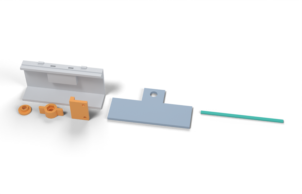
Print in ASA (TPU 85A for the seal), 0.2 mm layers, at least 4 walls; settings and the clearances used are in print/README.md. The parts are already turned the right way up for printing. The box and lid coupons are short test sections with this latch's box-side and lid-side features, so you can try the latch before building it into your own enclosure.
| File | Material | Qty | Size (mm) | How to print |
|---|---|---|---|---|
| housing.stl | ASA | 1 | 14 × 14 × 5 | Flange down, no supports. A bushing in the lid tab for the M5 screw. |
| knob.stl | ASA | 1 | 27 × 14 × 9 | Flat, no supports. An M5 × 40 socket screw comes up from below: its head and a nut clamp the pawl, a nut in the knob's hex pocket and a jam nut on top lock the knob to it. |
| ramp-keeper.stl | ASA | 1 | 19.2 × 7 × 28 | On its end, no supports. The underside ramps down 1.5 mm to a flat dwell; the block is the stop. 2 × M3 × 10 into the box. |
| box-coupon.stl | ASA | 1 | 90 × 24 × 41.6 | Upright, no supports. A section of box wall with this latch's box-side features: seal groove, hard stops, and an inside pillar with nut channels. Push an M3 square nut down each of the 2 channels in the rim before fitting the screws. Copy these features into your own box. |
| lid-coupon.stl | ASA | 1 | 90 × 50 × 3 | Flat, top up. A section of lid with this latch's lid-side features. Copy them into your own lid. |
| seal-strip.stl | TPU 85A | 1 | 90 × 3.4 × 1.5 | TPU 85A, 100 % infill, lying on its side. Press it into the rim groove: it stands 2.4 mm proud and the latch squeezes it 0.8 mm, until the lid lands on the hard stops. |
All printed parts in their assembled positions, for CAD: quarter-turn-compression.step.
How it works
A quarter turn of a key, knob or T-handle rotates a shaft. A helical ramp or cam in a panel-mounted housing converts the rotation into axial draw. A pawl on the shaft behind the panel hooks the frame and pulls the lid onto the gasket. Commercial versions (EMKA 1000, Southco E9) use a two-stage turn for 4-6 mm of travel against foam gaskets. A printed version replaces the knob, housing and ramp with printed parts on a steel shaft, nut and washers.
Mechanical advantage
Ramp: mean radius 10 mm, rise 1.5 mm over 90 degrees, tan(alpha) = 1.5/15.7 = 0.0955 (5.5 degrees). Frictionless MA = 25 mm hand radius / (10 mm x 0.0955) = 26. With mu = 0.3 (dry printed ASA on ASA, assumed) the real ratio is ~6:1 (33 N at 25 mm gives ~0.81 N*m, ~200 N). Lower than a screw or lift-and-turn latch because the ramp radius is small and friction is high. Self-locking requires mu > 0.0955.
What limits the force
The printed pawl and the printed frame ledge. The pawl must pass through the panel cutout (about 22-24 mm), so a printed pawl is small and weak in bending. A steel or hardened cam is needed. The ledge loaded through layers is the second limit. Also, the ramp stroke (4-6 mm commercial, 1-1.5 mm printed) is far from the 0.2-0.75 mm the gasket needs, so force depends on where the cam parks unless the ramp ends in a hard stop.
Analyst's calculation
Analyst's sustained estimate: 100–350 N, typical 200 N; peak 700 N.
[Web search budget was exhausted this run. No printed test was found. Commercial ratings come from the brief; I re-fetched the EMKA product page and the ElectronicSpecifier article.]
- Assumed printed analogue: steel M5 shaft with a nut and washers, printed T-knob or 50 mm wing (hand radius 25 mm), housing in a 24 mm panel cutout. Ramp pair at mean radius 10 mm, rise 1.5 mm over 90 degrees, radial width 6 mm, 12 mm arc each, area 2 x 72 = 144 mm2. Pawl bar 22 long, 10 wide, 8-14 thick.
- Ramp torque: T = Fr_m(tan a + mu)/(1 - mutan a) = F x 10 mm x 0.407 = 4.07 mm x F. For 200 N this is 0.81 Nm, ~33 N at 25 mm. With mu = 0.2 the factor is 0.30, and 200 N needs 0.60 N*m (24 N).
- Ramp bearing, load normal to layers (housing printed with its axis vertical): 144 mm2 x 6 MPa = 860 N. Not limiting.
- Printed pawl, three-point bending (F = 4sigmaZ/L, L = 16 mm). A 10 x 8 mm bar with a 5.3 mm hole: Z = (10-5.3) x 64/6 = 50 mm3. At 3 MPa that is only 37 N. At 14 mm thick, Z = 153 mm3 and F = 115 N. Hence a printed pawl alone gives ~100-150 N sustained.
- With a steel pawl (2-3 mm 304 stainless bar or plate, or a stainless T-head bolt), the limit moves to the frame ledge. Ledge shear across layers, 1.5V/A <= 2 MPa: A >= 1.5 x 200/2 = 150 mm2 for 200 N and ~260 mm2 for 350 N.
- Result: sustained 100 (printed pawl) / 200 (steel pawl, 150 mm2 printed ledge) / 350 N (steel pawl, steel keeper or insert boss). Peak ~700 N (range 500-1000): the ledge or pawl fails first.
- Commercial anchors, static and foam-gasket based: Essentra zinc quarter-turn compression lock 562 N max load at 6 mm compression, -50 to +80 C (from brief via search text). EMKA 1000-U805: 6 mm compression, IP65, PUR foam gasket, zinc body, no force rating on the page (verified). Second turn adds ~5.5 mm after a 3 mm ramp (verified). Southco E9 ~4 mm, IP66/IP67 (from brief; my fetch returned 403). These foam gaskets need roughly 0.2-1.4 N/mm, against 2-4 N/mm for the 85A design rib.
- Tolerance: a stroke-controlled ramp that ends at a fixed stop gives force proportional to stack-up error. +/-0.2 mm FDM tolerance on a 0.48 mm squeeze means roughly +/-40 % force. A nut on the shaft plus a wave spring would fix it but needs a 2.5-3 mm ramp rise.
- Retention: fixed-travel gives ~33-48 % loss after 70 C set (same chain as vise-action); ramp creep adds. Cold: ~2x force at -30 C.
Adversarial review
Independent recalculation. Ramp: arc = pi/2 x 10 = 15.7 mm, tan(alpha)=0.0955, T = F10(0.0955+0.3)/(1-0.02865) = 4.07 mm x F, checked. At 200 N: 0.81 N*m, 33 N at 25 mm, checked (24 N at mu=0.2). Printed pawl 10 x 8 mm: Z = 50 mm3, 37 N at 3 MPa; 10 x 14: Z = 153 mm3, 115 N. Ramp bearing 144 mm2 x 6 MPa = 860 N, not limiting, checked. The claim that foam gaskets need 0.2-1.4 N/mm against 2-4 N/mm for the 85A rib is plausible and unsourced; it explains why a latch rated for foam is poorly matched here. Commercial reference points verified: Southco N4 (600 N working, 1200 N ultimate, 300 N hand-turned compression force), M1 stainless long cam 350 N and short cam 1010 N max static. No printed quarter-turn test exists in the sources I could open. All values are estimates. This is the weakest of the four for the stated purpose (high sustained clamp on a TPU 85A gasket); its best role is as a convenient fastener on a soft low-load foam or thin-rib gasket.
Issues raised:
- Sustained 200 N typical is optimistic. The printed-pawl case (100-150 N: a 10 x 14 mm pawl with a 5.3 mm hole, Z = 153 mm3, F = 43153/16 = 115 N) is right. The 'steel pawl' tier then moves the limit to a printed ledge, which the analyst checks only in shear (150 mm2 gives 200 N). Root bending across layers (b=15, t=12, a=3-6 mm, 2 MPa) gives 120-240 N. Typical 150 N, and the 200-350 N tier needs a custom steel pawl plus a steel keeper or insert boss. A thin printed pawl (8 mm) gives 40 N, hence a low of 60 N.
- Operating force is understated. 4.07 mm x F (tan(alpha)=0.0955, 5.5 deg, MA 26 frictionless, 6:1 real) counts only the ramp. With a second sliding surface (about 1.8 mm x F), 150 N needs about 0.9 N*m, i.e. about 35 N on a 25 mm wing arm. 200 N would need 47 N, at the top of the 20-50 N comfort band.
- Peak 700 N is cut to 500 N. Printed ledge failure across layers is about 540 N at a=6 mm (9 MPa, the 29 % rule) and a printed pawl breaks lower. A zinc Southco N4 is rated 1200 N ultimate and a stainless M1 long cam 350 N static, so 700 N for a printed ASA copy is too close.
- The stroke is the wrong size. Commercial 4-6 mm travel against foam is replaced by a 1.5 mm printed ramp, and a ramp ending in a hard stop gives about +/-40 % force from the +/-0.2 mm FDM stack-up against a 0.48 mm squeeze. Without a detent the cam parks mid-ramp and the force is arbitrary. The latch also loses 33-74 % in hot sun (the analyst used 33-48 %).
- At 150 N each, the latch needs 19 units for 2.8 kN and 10 units for the 1.4 kN low window. It cannot fit a 70 mm body at those pitches, so it does not meet the reference requirement at 4-8 latches. Seal 5 stands. Durability 5: cam wear, a shaft hole that is a leak path, and a printed knob that cracks in the cold.
- Commercial anchors: EMKA 1000-U805 confirmed (6 mm compression, IP65, PUR foam, zinc die-cast, no force rating). ElectronicSpecifier confirmed 3 mm ramp then +5.5 mm and IP65, but dated 2011 and inconsistent with the EMKA page's 6 mm total. The Essentra 562 N / 6 mm / -50 to +80 C datasheet link on DigiKey is dead (HTTP 410), so that anchor is unverified. Southco E9 (IP66/IP67) returned 403.
Preload retention outdoors
Poor to fair as a fixed-travel latch: ~33-48 % loss after hot sun (gasket set 35-52 % plus ramp and pawl creep), unless a wave spring or disc stack is added under the shaft nut with a 2.5-3 mm ramp rise (then ~10-17 %). If the ramp is long and the cam parks mid-ramp, the force is friction-held and can back off. Add a detent.
Materials
ASA for the knob and housing. Use a steel or hardened stainless pawl or cam (a printed one is weak and the ramp wears). Avoid PETG and PETG-CF at 60-70 C. Avoid PA6-CF outdoors. UV-stabilised PC may give ~1.3-1.5x margin on printed parts (own judgement). Avoid unstabilised PP.
Hardware notes from the research
Flagged: not printed. A2/A4 stainless M5 shaft or stud, nut and washers (the nut sets the grip), a 304 stainless pawl or T-head, optional wave spring or Belleville stack, optional O-ring or boot for the shaft hole. Or buy the commercial EMKA, Southco or Essentra latch.
Design guidelines
- Housing and ramp: print with the axis vertical so the ramp load is normal to layers. Use a ramp rise of 1.5 mm for a rigid shaft (2.5-3 mm if a spring stack is fitted), mean radius 10 mm, arc >= 12 mm, radial width >= 6 mm, contact >= 140 mm2.
- End the ramp in a flat dwell of about 15 degrees plus a 0.3 mm detent. Without it the cam parks mid-ramp and the force becomes arbitrary, and it can back-drive under vibration.
- Pawl: use a steel bar if possible. A printed pawl needs >= 14 mm thickness and is still only ~100-150 N. Print it flat so bending runs along layers, with the hole axis along Z.
- Frame ledge: root section >= 150 mm2 (about 12 x 12 mm) for 200 N, with a root fillet >= 3 mm, or use a steel keeper or insert boss.
- Panel cutout 22-24 mm. Seal the shaft or cutout with an O-ring or a flange gasket. The hole is a leak path, and the commercial latches are rated IP65/66 only with their own gasket.
- Knob: a 50 mm wing or T-bar gives ~33 N hand force at 200 N. A coin slot or small key will not manage it. Hex or D-flat drive to the shaft.
- Add a printed land stop beside each latch at 0.75-0.8x the free bead height. The ramp alone does not define the squeeze.
- Set the grip with the shaft nut using a force gauge at mid-temperature. Do not rely on FDM tolerance.
Failure modes
- The printed pawl cracks at the shaft hole, or the ledge shears across layers.
- Ramp wear and creep: the ramp flattens and the draw is lost.
- The cam parks mid-ramp and the force is arbitrary.
- The latch back-drives under vibration or when greased.
- Force varies +/-40 % from FDM stack-up error.
- Gasket set at 70 C takes 33-48 % of a fixed-travel preload.
- Cold: force doubles at -30 C and the knob can crack.
- Shaft or cutout leak.
- Dirt in the ramp raises the friction.
Existing designs and commercial references
- EMKA 1000-U805 compression latch [COMMERCIAL, not printable] — Verified by fetch: 6 mm compression, IP65, PUR foamed gasket, zinc body, no force data.
- ElectronicSpecifier: EMKA compression latch article [COMMERCIAL reference] — Verified by fetch: 3 mm ramp on the first turn, ~5.5 mm further compression on the second, IP65.
- Southco E9-A005F-02 [COMMERCIAL, not printable] — ~4 mm compression, IP66/IP67 (from brief). My fetch returned 403.
Evidence gathered in the sweep
SUSTAINED (own est., printed knob/ramp on steel shaft): 150-400 N; PEAK ~500-1000 N. COMMERCIAL: Essentra zinc quarter-turn compression lock 562 N max load at 6 mm compression, -50 to +80 C https://www.digikey.cn/htmldatasheets/production/2905106/0/0/1/compression-cam-latch-datasheet.pdf (search text); EMKA 1000-U805 verified by me: 6 mm compression, IP65, PUR foamed gasket, no load rating given https://www.emka.com/products/1000-u805 ; EMKA second stage ~5.5 mm https://www.electronicspecifier.com/?p=113370 ; Southco E9 ~4 mm, IP66/IP67 https://southco.com/en_gb_int/e9-a005f-02 . All ratings assume foam gaskets (EMI low-closure gaskets are ~0.2-1.4 N/mm vs 85A TPU 4-12 N/mm). No printed pull-off test. Orientation: ramp faces in the XY plane. CONFIDENCE: low-medium.
Sources
- EMKA 1000-U805 compression latch — Verified by fetch. 6 mm compression, IP65, PUR foam, no force rating.
- ElectronicSpecifier: EMKA compression latch — Verified by fetch. 3 mm ramp, then 5.5 mm compression.
- Essentra compression cam latch datasheet (DigiKey) — From brief via search text, not re-fetched. 562 N at 6 mm, -50 to +80 C.
- Southco E9-A005F-02 — From brief; fetch returned 403.
- CNC Kitchen: comparing PLA, PETG and ASA (Prusament) — Verified by fetch. ASA hook lying 57 kg vs standing 17 kg. Used for the ledge anchor.
- CNC Kitchen: helicoils, threaded inserts and embedded nuts (PETG M3) — Verified by fetch. Insert in Z pull-out 119 kg.
- Texin 985 datasheet — From brief, not re-fetched. Compression set and cold modulus.
Sources the reviewer flagged (dead, blocked or misdescribed):
- https://www.digikey.cn/htmldatasheets/production/2905106/0/0/1/compression-cam-latch-datasheet.pdf : HTTP 410 Gone, the 562 N Essentra claim cannot be verified
- https://southco.com/en_gb_int/e9-a005f-02 : HTTP 403, E9 4 mm and IP66/IP67 unverified
- https://www.electronicspecifier.com/?p=113370 : dated 2011; 3 mm ramp plus 5.5 mm second turn does not match the EMKA page's 6 mm total compression
- https://www.emka.com/products/1000-u805 : confirmed, but gives no force rating