No. 07 of 20 · Rectangular lids
Over-center draw latch, screw-adjustable hook
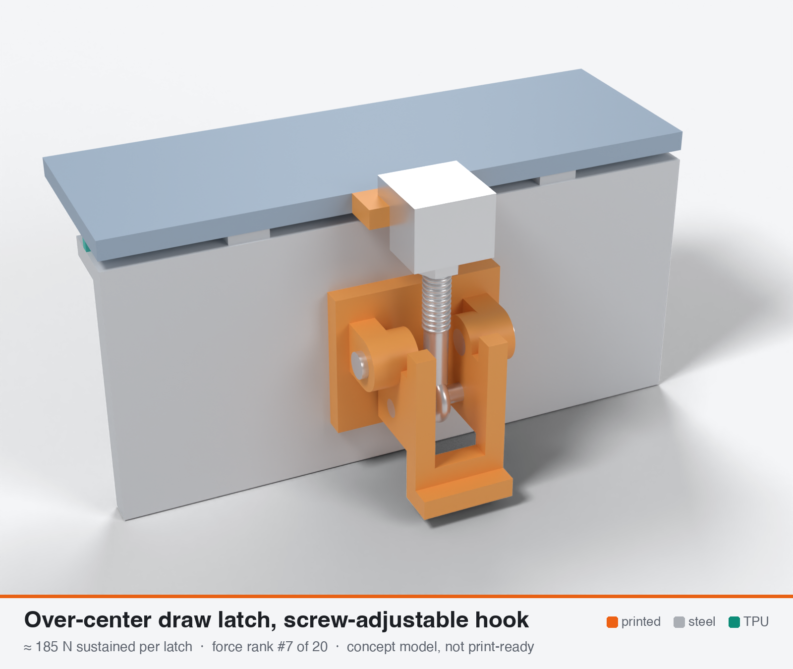
Over-center draw latch with steel threaded adjuster (re-tensionable hook)
Model note: In the 3D model the link pin on the lever sits about 0.8 mm nearer the wall than the line from the lever pivot to where the hook bears on the keeper. Opening the lever therefore pulls the link through dead centre, which is what makes the latch lock itself shut. With the pin on the far side of that line, the link's pull would push the lever open. The handle plate has a slot so the link can pass through it when the lever swings open.
- Force rank
- 7 of 20
- Rank for outdoor sealing
- 4
- Latches for the reference lid
- 8–16
- Build
- Printed + steel hardware
- Hand force to close
- ≈ 10 N
- Adjustable preload
- yes
- Positive compression stop
- no
- Force basis
- calculated
- Review verdict
- corrected
- Confidence
- low
Verdict: Over-center lever with a steel eye-bolt adjuster. About five printed failure modes (wall bearing, pin bores, lug, ear root, keeper) sit within about 1.4x of each other. Re-tensionable (0.2 turn restores hot-set loss) and quick to operate. A rigid link, so scheduled re-tensioning is required.
Why it ranks #4 for sealing: About 185 N (range 130-240) with the best operability of the lever types (about 10 N hand force, one motion). A steel eye-bolt re-tensions (about 0.2 turn restores a 37 % hot-set loss). Six to eight latches give about 1.9-2.6 N/mm, the bottom of the design window. Rigid, so expect to re-tension after the first hot weeks. Fit a locknut and a printed hard stop.
On this page
Parts
Per latch: 3 parts to print, 6 items to buy, 3 features printed into the box or lid and the TPU 85A seal. Parts marked † are not drawn in the 3D model. In the 3D gallery you can click a part to see where it sits. The last column links the print file, or an example of the part in a shop (see the shopping list).
| Part | Qty | Type | What to use | File or shop |
|---|---|---|---|---|
| Base | 1 | ASA, flat on its back; ears with 4.25 mm bores | base.stl | |
| Lever | 1 | ASA, on its side with supports under the upper cheek; 3.9 mm press holes for the pins | lever.stl | |
| Hook | 1 | ASA, upside down; sits on the keeper (a steel hook is stronger) | hook.stl | |
| Base screws † | 2 | Buy | M3 × 10 A2/A4 socket screws (DIN 912) | Grobotronics |
| Square nuts † | 2 | Buy | M3 square nuts (DIN 562), dropped down the channels in the box wall | Grobotronics |
| Pivot pins | 2 | Buy | 4 mm steel pins, 8 mm long, cut from 4 mm shaft; pressed into the lever cheeks, they turn in the base | Grobotronics |
| Link pin | 1 | Buy | 4 mm steel pin, 14 mm long; pressed through both cheeks | Grobotronics |
| Eye bolt | 1 | Buy | M4 × 40 A2/A4 eye bolt (DIN 444); the eye at most 10 mm across and 5.5 mm thick | Amazon.de |
| Nyloc nut and washer | 1 | Buy | M4 A2/A4 nyloc nut and washer on top of the hook; turning it sets the take-up | M4 nyloc · M4 screw |
| Keeper | 1 | Printed with the lid | Ledge on the lid edge, 18 × 6 mm, loaded in compression | lid-coupon.stl |
| Hard stops | 2 | Printed with the box | Pads on the rim either side of the latch, 1.6 mm tall: 0.8 mm below the free seal | box-coupon.stl |
| Nut channels | 2 | Printed with the box | Inside pillar with a 5.7 × 2.0 mm channel per nut, open on the rim outside the seal; blind 3.4 mm screw holes, so no path into the box | box-coupon.stl |
| Seal strip | 1 | Seal (TPU 85A) | TPU 85A, 1.5 × 3.4 mm, in a 1.8 × 1.0 mm groove in the rim; the latch squeezes it 0.8 mm | seal-strip.stl |
Print files
Download all print files for this latch (ZIP, 88 kB)
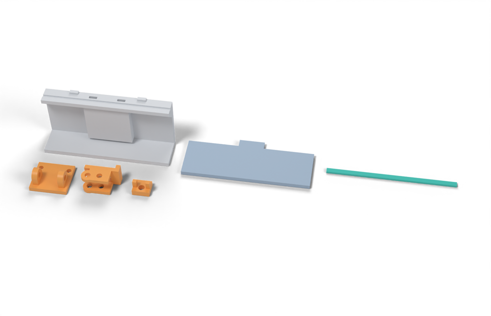
Print version: The hook is printed: a plate that sits on the keeper, with two legs against its edge. The M4 eye bolt passes through it and a nyloc nut on top sets the take-up.
Print in ASA (TPU 85A for the seal), 0.2 mm layers, at least 4 walls; settings and the clearances used are in print/README.md. The parts are already turned the right way up for printing. The box and lid coupons are short test sections with this latch's box-side and lid-side features, so you can try the latch before building it into your own enclosure.
| File | Material | Qty | Size (mm) | How to print |
|---|---|---|---|---|
| base.stl | ASA | 1 | 26 × 24 × 13 | Flat on its back, no supports. 2 × M3 × 10 into the box. The pivot pins turn in these bores. |
| lever.stl | ASA | 1 | 24.5 × 16.5 × 13.5 | On its side (pin axis vertical), supports under the upper cheek. Press the pivot pins and the link pin into the 3.9 mm holes. |
| hook.stl | ASA | 1 | 12 × 10.5 × 9.1 | Upside down, no supports. Sits on the keeper; the M4 eye bolt passes through it and an M4 nyloc nut with a washer on top sets the take-up. A steel hook is stronger. |
| box-coupon.stl | ASA | 1 | 90 × 24 × 41.6 | Upright, no supports. A section of box wall with this latch's box-side features: seal groove, hard stops, and an inside pillar with nut channels. Push an M3 square nut down each of the 2 channels in the rim before fitting the screws. Copy these features into your own box. |
| lid-coupon.stl | ASA | 1 | 90 × 36 × 3 | Flat, top up. A section of lid with this latch's lid-side features. Copy them into your own lid. |
| seal-strip.stl | TPU 85A | 1 | 90 × 3.4 × 1.5 | TPU 85A, 100 % infill, lying on its side. Press it into the rim groove: it stands 2.4 mm proud and the latch squeezes it 0.8 mm, until the lid lands on the hard stops. |
All printed parts in their assembled positions, for CAD: oc-adjustable-screw-hook.step.
How to assemble
This follows the print files and the parts list above. They are first prototypes, so do one test assembly, on the box and lid coupons, before printing a full set.
Tools: a 2.5 mm hex key, a 7 mm spanner (M4 nuts), a cut-off disc for the pins, a file, a vise with soft jaws, a 4.2 or 4.3 mm drill, calipers and a feeler gauge.
1. Print and prepare
- Print
base.stlflat on its back,lever.stlon its side (with supports under the upper cheek) andhook.stlupside down, all in ASA, as they come. - Print the box with the two hard stops and the nut channels, and the lid with its keeper ledge, or the box and lid coupons to try it first.
- Cut three pins from the 4 mm shaft: two 8 mm long (the pivots) and one 14 mm long (the link pin). The shaft is hardened, so use a cut-off disc, not a hacksaw. Chamfer the ends with a file so they press in straight.
- Run the 4.2 or 4.3 mm drill through both ears of the base so the pivot pins turn freely there. Don't drill the lever: its 3.9 mm holes are meant to grip the pins.
- Check the M4 eye bolt fits between the lever cheeks (8.5 mm gap) and that its eye takes a 4 mm pin.
- Check the lid on the bare box: it should rest on the TPU rib with about a 0.8 mm gap above the hard stops. If it already touches the stops, the rib is too low and won't seal.
2. Base
- Drop 2 M3 square nuts down their channels from the rim.
- Screw the base to the box with 2 M3 × 10 screws, ears outward, snug but not hard.
3. Lever and link
- Hold the eye of the eye bolt between the lever cheeks, at the lower holes. Press the 14 mm link pin through cheek, eye and cheek in the vise until it's flush on both sides. The eye must turn freely on the pin.
- Put the lever's cheeks between the base ears, pivot holes lined up. Press an 8 mm pin through each ear into the cheek, from the outside, until its inner end is flush with the inside face of the cheek. The pins grip the cheeks and turn in the ears; the lever should swing freely.
4. Hook and take-up
- Close the lid. Swing the lever up and put the hook on the keeper ledge, its two legs against the ledge's edge, with the eye bolt coming up through its hole.
- Put an M4 washer and the nyloc nut on the eye bolt.
- With the lever open (swung out), turn the nut down until the lever just starts to resist at the very end of its travel as you close it. That's zero.
- Open the lever and tighten the nut another quarter turn (0.18 mm on M4). Repeat, a quarter turn at a time, until closing the lever pulls the lid onto the hard stops and the lever snaps over centre with a firm push, about 10 N at the end of the handle. With the 0.8 mm seal squeeze that takes about 1¼ turns from zero; add one more quarter turn of preload.
- Check with the latch closed:
- The lever has gone over centre: it stays shut when you pull the hook up, and pushing the handle further does nothing.
- The lid sits on the hard stops: a 0.05 mm feeler gauge won't go in.
- If the lever won't go over centre, back the nut off a quarter turn.
5. Final checks
- Open and close it a few times. Open, the hook should lift off the keeper; the slot in the handle lets the eye bolt through as the lever swings.
- Fit every latch the same way; the reference lid needs 8–16. Close them in a cross pattern.
- This latch has no spring, so the seal's set after the first hot weeks costs a lot of force. Check then, and take up the play with the nut, about a quarter turn.
How it works
A flat printed lever pivots on a stainless pin (P1) in a printed base. A second pin (P2), offset e = 10 mm from P1, carries a steel threaded link (DIN 444-type eye-bolt, or an M4/M5 screw with lock nut) that reaches the keeper on the lid. Closing swings P2 through dead centre (keeper-P1 line) to about 0.7 mm over-centre against a printed lever stop, so the hook load itself holds the lever shut and no friction is needed. Clamp force is set by take-up beyond gasket contact times the series stiffness of gasket and latch, not by hand force. The screw trims take-up to the 0.2-0.75 mm a TPU bead needs and re-tensions after compression set. The printed hook root is out of the load path; only printed pivot bores, base ears and the wall mount carry load.
Mechanical advantage
Lever 60 mm, eccentric e = 10 mm (own calc). Static MA at the lock position (phi about 4 deg, 0.7 mm over-centre) = L/(e sin phi) = 60/0.7, about 86:1. Worst point of the closing stroke (1 mm engagement stroke, M_max = 0.385 x F x e x phi_c): about 35:1 geometric, about 22:1 after pivot friction (mu 0.25 steel pin in ASA). Screw: M4 x 0.7 gives 0.7 mm of hook take-up per turn; 1/8 turn = 0.09 mm = about 51 N of clamp force at 587 N/mm series stiffness.
What limits the force
Printed ASA, not the steel: bearing of the two 4 mm pin joints in printed bores and, first of all, bearing of the base screws in a 3-4 mm enclosure wall (2 x M4, 28 mm2). Thickening the mount pad to 6 mm moves the limit to the lever pin bore (about 290 N typical). All limits are ASA creep at 60-70 C, so sustained is roughly one third of peak.
Analyst's calculation
Analyst's sustained estimate: 170–280 N, typical 225 N; peak 700 N.
DIMENSIONS (my choice, inside 70 x 35 x 30): flat lever plate 9 mm thick (pin axes along Z, printed flat), handle 60 mm from P1, e = 10 mm, A4 stainless 4 mm pins in double shear, lug boss OD 14 mm, base = two ears 5 mm each with 25 mm root width and 12 mm standoff, steel M5 eye-bolt, base screwed to a 3.5 mm wall with 2 x M4. ALLOWABLES (working rule from the brief, ASA at 60-70 C, safety factor already inside): in-plane net section 3 / 4 / 5.5 MPa; pin bearing 6 / 8 / 10 MPa; across layers 2 MPa (avoided by orientation). LIMIT CHECKS, low / typical / high:
- lever bore bearing 4 x 9 = 36 mm2 -> 216 / 288 / 360 N
- base ear bearing 2 x (4 x 5) = 40 mm2 -> 240 / 320 / 400 N
- lever lug net section (14-4) x 9 = 90 mm2 -> 270 / 360 / 495 N
- ear root in-plane bending, sigma = 6 x (F/2) x 12 / (5 x 25^2) = 0.0115 F -> 260 / 348 / 478 N
- wall bearing under 2 x M4, 4 x 3.5 x 2 = 28 mm2 -> 168 / 224 / 280 N <- governs
- A4 pins (2 x 12.6 mm2 shear), M5 eye-bolt and an M4 heat-set insert (PETG M3 insert pulls out at about 1.17 kN per the CNC Kitchen test) are all several times stronger and do not govern. Result: sustained 170 / 225 / 280 N. With a 6 mm pad (48 mm2) the lever bore governs: 216 / 288 / 360 N. PEAK (short-term break, 23 C): wall bearing 28 mm2 x about 25 MPa = 700 N; lever bore 36 x 28 = about 1.0 kN; lug 90 x 14 = about 1.26 kN. Report 700 N (500-1000). HAND FORCE: moment at the worst point = (1.72 F geometric + 1.0 F pin friction) mm = 2.72 F mm; at F = 225 N and a 60 mm lever that is about 10 N. FIT TO LOAD: 6 latches x 225 N = 1.35 kN on the 700 mm path = 1.9 N/mm (bottom of the 2-4 N/mm window); 8 latches = 1.8 kN = 2.6 N/mm. It cannot deliver the 467-700 N per latch a solid 3 mm bead needs. BENCHMARKS: Southco E8 plastic adjustable draw latch is rated 1560 N working load (from the brief, not re-fetched); DE-STA-CO 341 steel 2000 lbf with 0.76 in max hook adjustment (fetched); Camloc 95L 220 N working vs 445 N max (fetched); steel Ganter GN 850-500 5000 N. The printed version is 5-7x lower than injection-moulded GF nylon because ASA is weak across layers and creeps hot. EVIDENCE STATUS: no printed sustained test found; the web-search budget was exhausted in this run, so no new tests of this mechanism were located. Confidence low-medium.
Adversarial review
Recomputed independently in Python. Limit-state results (low/typ/high, N): wall bearing 168/224/280, lever bore 216/288/360, ears 240/320/400, lug 270/360/495, ear root 261/348/478. These match the analyst. Pin bending (my addition): 534 N.mm at 225 N, about 85 MPa on a 4 mm A4 pin, so the pin is fine (about 3x margin on 316 yield). I then applied Kt 1.5 to lug and ear root (180/240/330 and 174/232/319), a 0.9 factor for several co-governing limits, and a 0.9 factor for the unchecked keeper side. The typical is then 224 x 0.81, about 185. The low and high are 130 and 240. The result is 18 % below the analyst, so this is a trim rather than a refutation. The sustained values rest on the brief's unvalidated ASA rule (3-5 MPa in-plane, 8-10 MPa bearing). Dogan 2022, which I decoded, used milled specimens for 3 h: ABS survived 10 MPa at 60 C and ruptured at 20 MPa in about 3 min. It supports the order of magnitude but not months of life. Peak is trimmed from 700 to 600 N because 25 MPa bearing on 4 mm screws in a 3.5 mm printed wall is the optimistic end. Hot-case caveat: gasket set and softening unload a rigid latch to about 0.5-0.6 of its as-set force, so the hot allowable is conservative for the initial assembly load. Cold +63 % force at fixed stroke is verified (2.2x modulus is in the Texin sheet). Scores: seal 7 to 6 (depends on maintenance re-tensioning and hits only the bottom of the 2-4 N/mm window at 6 latches). Durability 7 to 6 (no outdoor or creep test of this mechanism exists). Usability 8 to 7. Rank by delivered end-of-life force, assuming re-tensioning: the screw latch is first or second with the spring latch. The ranking is more robust than the absolute numbers, which are about +/-2x.
Issues raised:
- The arithmetic reproduces to under 1 %: lever bore 36 mm2, base ears 40 mm2, lug 90 mm2, ear root coefficient 0.0115, wall 28 mm2, MA 60/1.72, series stiffness 587 N/mm, set loss 0.71 s, cold +63 %. The dispute is with the allowables and the omissions, not the maths.
- Lug net section and ear-root bending are checked at nominal stress with no stress concentration. A pin lug has Kt of about 2.5 and a filleted ear root about 1.5-2. With an effective Kt of only 1.5 they drop to 240 N and 232 N typical, within 5 % of the 224 N wall-bearing limit. Five failure modes then sit within about 1.4x of each other, so system capacity is below the single smallest limit.
- The keeper and lid-side path (keeper pin, ears, flange fixing) carries the same F but is never checked. The text says only the pivots, ears and wall carry load.
- Prying moment on the base is ignored. The pivot sits 12-15 mm off the wall, so F x 12-15 mm puts about 80-120 N of tension on one insert or screw at 185-225 N. The 'several times stronger' claim for inserts cites a 1.17 kN M3-in-PETG pull-out on flat coupons at room temperature. That is a peak value, not hot or sustained, and not ASA. Hot, sustained pull-out is probably 150-250 N, so the margin is about 1.5-2x, not several.
- Creep relaxation is assumed to be only 0.02-0.05 mm (12-30 N). If bearings and the lug sit at the working-rule stresses, about 1 % creep strain on a 15 mm lug alone is 0.15 mm, or about 90 N at 587 N/mm. 0.1-0.2 mm total (60-120 N) is more realistic, on top of the 37 % gasket-set loss. Scheduled re-tensioning is therefore mandatory, not optional. This does not change the capacity number but weakens the seal and durability scores.
- Hand force is overstated. The 1 mm engagement stroke belongs to a 587 N peak. At 225 N the stroke is 0.38 mm, giving geometric moment 1.07 F and about 8 N hand force. This is conservative and harmless.
- Camloc 95L: the page labels 445 N as tensile strength, not 'max load' (mild misquote). The Camloc is a stamped steel latch at 220 N working load, so a printed ASA latch matching it at 225 N sustained is optimistic.
- The US 4540206 patent (checked on Google Patents) describes a threaded link in compression when latched. The design here uses a tension eye-bolt, so the patent does not corroborate it, and it has no force numbers.
- A printed hard stop beside the latch does not relieve a rigid latch. Over-tightening against the stop still loads the printed parts past the allowable. The stop protects the gasket, not the latch.
- The E8 benchmark (1560 N, '5-7x lower') could not be fetched, so that comparison is unverified.
Preload retention outdoors
Rigid steel link: structure stiffness k_l about 2000 N/mm (assumed) in series with the gasket share k_g about 830 N/mm per 100 mm of pitch (own calc: 4 N/mm over a 0.48 mm squeeze x 100 mm). Set loss = s x k_l/(k_l + k_g) = 0.71 s. Ultrafuse 85A set 52 % at 70 C gives 37 % loss; 26 % at 23 C gives 18 %; Texin moulded 40-80 % at 70 C gives 28-57 %. ASA bearing creep of 0.02-0.05 mm adds 12-30 N (assumed; PETG bolted joints lost 11.5 % preload in 7 days vs 3 % for PLA, https://filamentspecs.com/creep-resistance-3d-printed-parts/). Cold: with 2.2x gasket modulus at -30 C the force at fixed stroke rises about 63 % (587 -> 955 N/mm). Expect about 55-65 % of the as-set preload after the first hot weeks if never re-tensioned; about 0.2 turn of an M4 (83 N / 587 N/mm = 0.14 mm) restores a 37 % loss. The steel link does not creep; use a lock nut or thread-lock.
Materials
ASA is the default (HDT 100 C, 1000 h QUV -3 % break stress). UV-stabilised PC probably raises the sustained limits about 1.3-1.5x (my judgement, unmeasured) and has the best creep margin. PETG and PETG-CF are marginal for sustained load at 60-70 C (HDT 68 C). PA6-CF is out (3.33 % water uptake, -22 % strength, -24 % modulus). PAHT-CF is acceptable but still creeps. Metal parts A4/A2 stainless.
Hardware notes from the research
Two A4 stainless 4 mm clevis or dowel pins (or M4 shoulder screws) with e-clips, one A4 DIN 444-type M5 eye-bolt (or M4/M5 screw) with a lock or nyloc nut and a 12 mm OD washer, a stainless 4 mm keeper pin or printed keeper ledge loaded in compression, 2 x M4 heat-set inserts (or screws with washers) for the base, optional compression spring. Flagged: this design depends on purchased hardware for the load path.
Design guidelines
- Pin axes along Z; lever, link and base ears printed flat so every load is in the XY layer plane. Never load a hook root or ear across layers (ASA keeps only 29 % of flat strength in the CNC Kitchen hook test).
- 4 mm A4 pins, bores printed at 4.2-4.3 mm; lever 9 mm thick, boss OD at least 14 mm (3.5x the pin), base ears 5 mm each, ear root at least 25 mm wide with a standoff of 12 mm or less.
- 4-5 perimeters (1.6-2 mm wall) around every bore, 100 % infill in the lug and ear zones, 0.15-0.2 mm layers; internal fillets R 2 mm or more (ASA notched Charpy is only 3 kJ/m2 at -30 C).
- Over-center geometry: e = 10 mm, lock offset 0.6-0.8 mm (about 4 deg) against a printed lever stop; screw range at least 2 mm so one latch covers tolerance plus set.
- Add a printed hard stop beside every latch at 0.75-0.8x the free bead height so over-tightening cannot crush the gasket; adjust to the stop with the lock nut, not by feel.
- Mount pad on the enclosure at least 6 mm thick with two M4 inserts 25-30 mm apart; the wall bearing is the weakest link otherwise. Corner and end latches may see +20-30 % load.
- Use A4 hardware with anti-seize on the eye-bolt thread; re-tension about 0.2 turn after the first hot week and check yearly.
Failure modes
- Wall or ear bearing creep: the pin bores and screw holes slowly ovalise at 60-70 C, so preload drifts down and the lever eventually walks out of over-centre.
- Over-tightened screw crushes the TPU rib or cracks the ear root; cold makes it worse because the gasket force can be about 60 % higher at fixed stroke.
- Compression set of the 85A bead (up to 52 % at 70 C) loses 30-40 % of preload; without re-tensioning the enclosure weeps.
- Vibration or thermal cycling lifts the lever out of the over-center lock (Ganter notes shock and vibration reduce holding capacity); needs a lever stop and a positive catch.
- Stainless thread galling or seizure, or dirt fouling in the eye-bolt thread.
- Brittle cracking at sharp inner corners in ASA below -20 C.
Existing designs and commercial references
- MakerWorld Self-Locking Toggle Latch 1054989 — closest printed starting point: 3 mm steel/stainless pins and a 2 mm TPU pad; fixed hook, no adjuster, no force data (carried from the brief, page not re-fetched, HTTP 403)
- M3 Toggle Latch High Performance (STLFinder) — M3 hardware; claims more than 10 kg (about 98 N); no adjuster (carried from the brief, HTTP 403)
Evidence gathered in the sweep
SUSTAINED (own est., ASA): 150-300 N; PEAK ~500-900 N. PLASTIC BENCHMARK: Southco E8 1560 N max working load, -29 to 80 C, ~7.9 mm adjustment https://southco.com/en_gb_int/E8 and https://pdf.nauticexpo.com/pdf/southco/e8-adjustable-style-draw-latches/22514-91220.html (search text). STEEL (not printable): Ganter GN 850-500 5000 N, GN 853-160 1750 N, GN 851-160 1600 N (https://www.ehorst.de/en/Verschluss-Spanner-mit-Zuganker-GN-850-1-500-TG-mit-Gegenhalter-1398999.html ); Kipp K0080 1800 N traction (https://www.marek.eu/data/katalogove-listy/kipp/K0080.pdf ); Misumi 1630 N (https://my.misumi-ec.com/vona2/detail/110310215549/ ); DE-STA-CO 331 700 lbf (~3.1 kN) https://destaco.com/productdetails.331.html , 341 2000 lbf (~8.9 kN) https://destaco.com/productdetails.341.html ; Camloc working load is 0.5-0.67 of max (95L 220/445 N) https://efc-intl.com/printitems/metal-access-fasteners/camloc-95l-series-tension-draw-latches ; Ganter notes vibration and shock reduce holding capacity. Patent: threaded link is in compression when latched https://patents.justia.com/patent/4540206 . Ideal toggle gain 1/(2 tan theta): ~14:1 at 2 deg, ~5.7:1 at 5 deg (own calc; the Firgelli page I fetched gives no such formula and says real force depends on geometry and stiffness). Insert pull-out is not limiting (M3 PETG 1.17 kN). No printed sustained test. CONFIDENCE: low-medium.
Sources
- DE-STA-CO 341 draw latch — fetched: 2000 lbf max holding capacity, 0.76 in max hook adjustment, 2.5 in draw movement
- Camloc 95L tension draw latches (EFC) — fetched: 220 N working load vs 445 N max, self-compensating spring-steel drawhook
- Southco E8 adjustable draw latches — 1560 N working load, about 7.9 mm adjustment; carried from the brief, page returns 403
- Ganter GN 850-500 (ehorst) — 5000 N holding force; carried from the brief
- CNC Kitchen: comparing PLA, PETG and ASA (hook tests, oven test) — fetched: ASA hook lying 57 kg vs standing 17 kg; 30 C chamber 20 kg; ASA fails 120 C loaded
- CNC Kitchen: threaded inserts and embedded nuts — M3 heat-set insert in PETG pulls out at 119 kg; carried from the brief, not re-fetched
- Texin 985 datasheet (85A TPU) — compression curve, set 40-80 % at 70 C, modulus 2.2x at -30 C; values taken from the brief
- Ultrafuse TPU 85A TDS — compression set 26 % at 23 C, 52 % at 70 C; values taken from the brief
- Creep resistance of 3D printed parts (filamentspecs) — fetched: bolted PETG lost 11.5 % clamp force in 7 days vs 3 % for PLA; no ASA data
- Adjustable draw latch US 4540206 — threaded link in compression when latched; carried from the brief, page returns 403
Sources the reviewer flagged (dead, blocked or misdescribed):
- https://southco.com/en_gb_int/E8 (HTTP 403 to automated fetch; the 1560 N and 7.9 mm figures are unverified)
- https://makerworld.com/en/models/1054989-self-locking-toggle-latch (HTTP 403; unverified)
- https://www.stlfinder.com/model/m3-toggle-latch-high-performance-wkO8uZca/4063366 (HTTP 403; the 10 kg claim is unverified)
- https://efc-intl.com/printitems/metal-access-fasteners/camloc-95l-series-tension-draw-latches (opens; 445 N is listed as tensile strength, not 'max load')
- https://patents.justia.com/patent/4540206 (403 on Justia; the Google Patents copy opens, shows a compression link, and has no force numbers)
- https://www.cnckitchen.com/blog/helicoils-threaded-insets-and-embedded-nuts-in-3d-prints-strength-amp-strength-assessment (opens and the numbers are right, but they are M3 in PETG on flat coupons, with wall thickness and temperature not stated; not valid as a hot, sustained, ASA margin)
- https://filamentspecs.com/creep-resistance-3d-printed-parts/ (opens; 11.5 % PETG vs 3 % PLA is right, but the page warns the figures are study-specific, gives no temperature, and has no ASA data)
- https://www.dream3d.co.uk/wp-content/uploads/2022/12/Ultrafuse_TPU_85A_TDS_EN_v2.5.pdf (PDF text not machine-readable here; set values 26 %/52 % not re-checked)