No. 08 of 20 · Rectangular lids
Over-center latch, spring-loaded
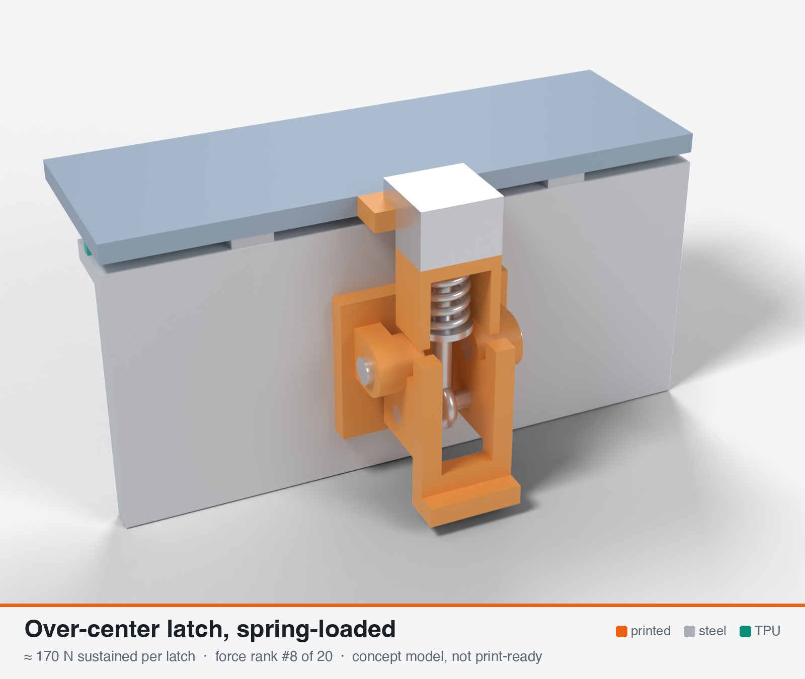
Spring-backed over-center latch (steel spring in series; stored-energy or ratchet-stop gasket compensating)
- Force rank
- 8 of 20
- Rank for outdoor sealing
- 5
- Latches for the reference lid
- 9–17
- Build
- Printed + steel hardware
- Hand force to close
- ≈ 13 N
- Adjustable preload
- yes
- Positive compression stop
- no
- Force basis
- calculated
- Review verdict
- corrected
- Confidence
- low
Verdict: Same printed limits as the screw-hook version, minus a knock-down for the carriage and guides. Best end-of-life retention of the over-center types (about 92 % kept). Fit in the envelope is unproven, and the exposed spring and guide are weak outdoors.
Why it ranks #5 for sealing: About 170 N (range 120-220), but it keeps about 92 % of its preload after hot set (rigid latches keep about 63 %) and the cold rise is only about 10 %. Needs 8 or more latches to reach the lower window edge. Printability 6, exposed spring and sliding carriage lower durability to 5, and fit in 70x35x30 mm is not demonstrated. A steel stop is needed so the spring cannot coil-bind.
On this page
Parts
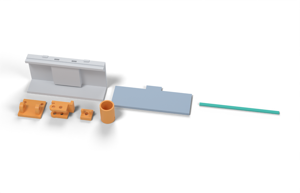
Per latch: 4 parts to print, 7 items to buy, 3 features printed into the box or lid and the TPU 85A seal. Parts marked † are not drawn in the 3D model. In the 3D gallery you can click a part to see where it sits. The last column links the print file, or an example of the part in a shop (see the shopping list).
| Part | Qty | Type | What to use | File or shop |
|---|---|---|---|---|
| Base | 1 | ASA, flat on its back; ears with 4.25 mm bores | base.stl | |
| Lever | 1 | ASA, on its side with supports under the upper cheek; 3.9 mm press holes for the pins | lever.stl | |
| Hook | 1 | ASA, upside down; sits on the keeper and carries the spring carriage | hook.stl | |
| Spring carriage | 1 | ASA, upright; holds the 12.5 × 25 mm die spring and stops it after 5.5 mm of travel, drain hole | spring-carriage.stl | |
| Base screws † | 2 | Buy | M3 × 10 A2/A4 socket screws (DIN 912) | Grobotronics |
| Square nuts † | 2 | Buy | M3 square nuts (DIN 562), dropped down the channels in the box wall | Grobotronics |
| Pivot pins | 2 | Buy | 4 mm steel pins, 8 mm long, cut from 4 mm shaft; pressed into the lever cheeks, they turn in the base | Grobotronics |
| Link pin | 1 | Buy | 4 mm steel pin, 14 mm long; pressed through both cheeks | Grobotronics |
| Eye rod | 1 | Buy | M4 × 70 A2/A4 eye bolt (DIN 444 style), at least 66 mm from the eye's centre to the end, or M4 threaded rod with a bent eye | Amazon.de |
| Compression spring | 1 | Buy | ISO 10243 die spring for a 12.5 mm hole, 25 mm long, yellow (extra heavy, about 58 N/mm); squeezed 3.4 mm when closed | Berner & Straller |
| Nyloc nut and washer | 1 | Buy | M4 A2/A4 nyloc nut, with a 15 mm washer under it (M5 DIN 9021) that lands on the carriage rim if the spring is squeezed too far | M4 nyloc · washer |
| Keeper | 1 | Printed with the lid | Ledge on the lid edge, 18 × 6 mm, loaded in compression | lid-coupon.stl |
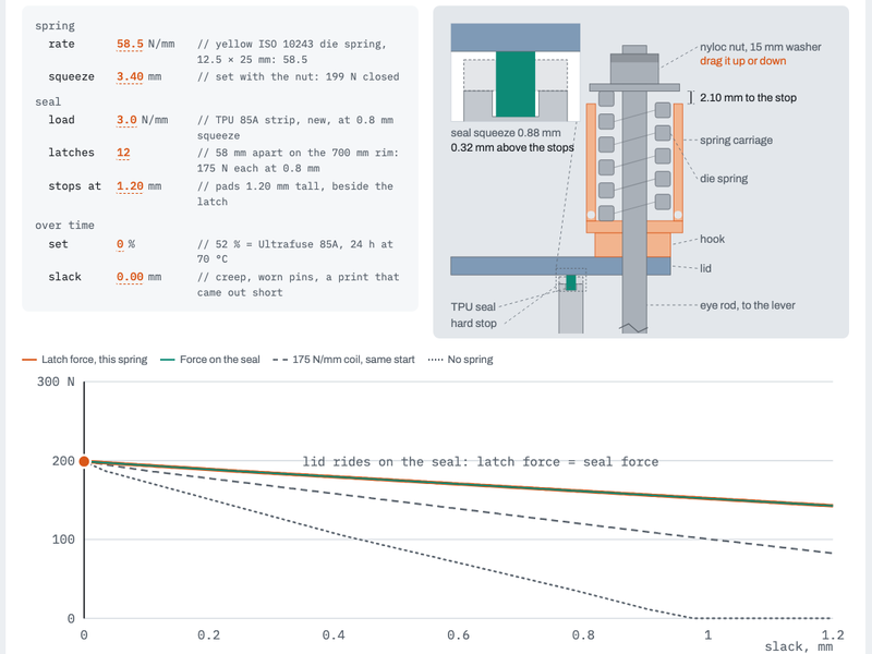
| Hard stops | 2 | Printed with the box | Pads on the rim either side of the latch, 1.2 mm tall: 1.2 mm below the free seal, so the spring sets the squeeze and the lid only reaches them once the seal has set | box-coupon.stl |
| Nut channels | 2 | Printed with the box | Inside pillar with a 5.7 × 2.0 mm channel per nut, open on the rim outside the seal; blind 3.4 mm screw holes, so no path into the box | box-coupon.stl |
| Seal strip | 1 | Seal (TPU 85A) | TPU 85A, 1.5 × 3.4 mm, in a 1.8 × 1.0 mm groove in the rim; the spring squeezes it about 0.9 mm | seal-strip.stl |
Print files
Download all print files for this latch (ZIP, 0.1 MB)
Print version: The spring is a stock ISO 10243 die spring (yellow, 12.5 mm hole, 25 mm long, about 58 N/mm) instead of the 175 N/mm coil in the analysis below. It sits on top of the printed hook, in the printed carriage, under a 15 mm washer and nyloc nut on the eye rod, so it is squeezed when the latch pulls: 3.4 mm for 200 N. Being softer, it loses less force when the loop slackens (creep, wear, a part printed short): about 6 N per 0.1 mm instead of 16 N. The hard stops are 1.2 mm tall, 0.4 mm lower than on the other latches, so on a new seal the lid floats about 0.3 mm above them and the spring alone sets the squeeze. As the seal sets, the lid follows it down: at the datasheet's 52 % set it lands on the stops with the seal still pressed at about 1.8 MPa, where stops at the usual height would leave 0.9 MPa, under the 1.4 MPa an elastomer gasket needs. The stops still keep the squeeze under 35 % if the lid is pressed down. Closing takes about twice the work of the coil (0.43 J against 0.20 J), over a longer pull.
Print in ASA (TPU 85A for the seal), 0.2 mm layers, at least 4 walls; settings and the clearances used are in print/README.md. The parts are already turned the right way up for printing. The box and lid coupons are short test sections with this latch's box-side and lid-side features, so you can try the latch before building it into your own enclosure.
| File | Material | Qty | Size (mm) | How to print |
|---|---|---|---|---|
| base.stl | ASA | 1 | 26 × 24 × 13 | Flat on its back, no supports. 2 × M3 × 10 into the box. The pivot pins turn in these bores. |
| lever.stl | ASA | 1 | 24.5 × 16.5 × 13.5 | On its side (pin axis vertical), supports under the upper cheek. Press the pivot pins and the link pin into the 3.9 mm holes. |
| hook.stl | ASA | 1 | 12 × 12.6 × 9.1 | Upside down, no supports. Sits on the keeper; the M4 eye bolt passes through it and the spring carriage sits on top. |
| spring-carriage.stl | ASA | 1 | 16 × 16 × 21.5 | Upright, no supports. Holds an ISO 10243 die spring for a 12.5 mm hole, 25 mm long (yellow, about 58 N/mm). Set the nut so that, closed, the 15 mm washer under it is about 2 mm above the rim: the spring is then squeezed 3.4 mm, about 200 N. The washer lands on the rim at 5.5 mm (about 320 N), short of the spring's 6.3 mm limit. The cross hole drains water. |
| box-coupon.stl | ASA | 1 | 90 × 24 × 41.2 | Upright, no supports. A section of box wall with this latch's box-side features: seal groove, hard stops, and an inside pillar with nut channels. Push an M3 square nut down each of the 2 channels in the rim before fitting the screws. The hard stops are 1.2 mm tall, 0.4 mm lower than on the other latches, so the spring, not the stops, sets how hard the seal is pressed. Copy these features into your own box. |
| lid-coupon.stl | ASA | 1 | 90 × 36 × 3 | Flat, top up. A section of lid with this latch's lid-side features. Copy them into your own lid. |
| seal-strip.stl | TPU 85A | 1 | 90 × 3.4 × 1.5 | TPU 85A, 100 % infill, lying on its side. Press it into the rim groove: it stands 2.4 mm proud and the spring squeezes it about 0.9 mm. The lid reaches the hard stops only at 1.2 mm, once the seal has set or if something presses on the lid. |
All printed parts in their assembled positions, for CAD: oc-spring-loaded-compensating.step.
How it works
The same printed lever and pins as an over-center draw latch, but the closing load passes through a stainless coil spring, disc stack or spring-steel hook in series with the gasket. The spring is about 5x softer than the gasket, so compression set, thermal movement and plastic creep change the preload only slightly. Variants: a sprung carriage that follows an ageing gasket and is held by a toothed or ramped stop (ITW US 8376418); a stored-energy spring that is cocked on opening and pulls the lid in past the balance point (ITW US 9370294, a toggle arm holds the cocked spring and releases it over-centre); a self-compensating spring-steel drawhook (Camloc 95L). Needs about 3 mm of hook travel for about 0.5 mm of gasket squeeze and a hard stop beside the latch.
Mechanical advantage
Lever 60 mm, e = 12 mm, engagement stroke 2.5 mm (my calc, the spring needs the extra travel): geometric MA at the worst point = 60/2.98 = 20:1; about 15:1 after pin friction. Static MA at lock about 100:1. The force the user feels is spring rate x deflection: with the 175 N/mm spring below, 200 N needs 1.14 mm of spring deflection plus 0.24 mm of gasket squeeze.
What limits the force
The same printed pivot and mount limits as the screw-adjusted latch (4 mm pins, 3.5 mm wall), reduced by about 10 % because the sprung carriage, guide ribs and spring housing take envelope and add stress raisers. The latch needs more stroke (about 3 mm) than the other types. The steel spring itself is not the limit.
Analyst's calculation
Analyst's sustained estimate: 150–250 N, typical 200 N; peak 600 N.
SPRING (own design): 302/304 or 316 stainless compression coil, wire d = 3.0 mm, mean diameter D = 11 mm, 3 active coils, G = 69 GPa (assumed). Rate k_s = G d^4/(8 D^3 Na) = 69000 x 81/(8 x 1331 x 3) = 175 N/mm. At 250 N: deflection 1.43 mm, Wahl factor K = 1.45 (index 3.67), shear tau = K x 8 F D/(pi d^3) = 376 MPa. Solid height 5 x 3 = 15 mm, so the free length is about 20 mm and the carriage stop is set at 1.8-2.0 mm of deflection (about 315-350 N cap). The cap protects the printed parts from over-closing. Confirm the allowable with the spring maker (stainless is 25-30 % weaker than music wire per Lee Spring). SERIES STIFFNESS: structure (hook, pins, ears, wall) k_l = 2000 N/mm (assumed) in series with the spring -> 161 N/mm; in series with the gasket (830 N/mm per 100 mm pitch) -> 135 N/mm. Take-up for 200 N: 200/135 = 1.5 mm; add 1.0 mm for set and tolerance, giving the 2.5 mm engagement stroke and about 3 mm of hook travel. PRINTED PARTS: same as the screw-adjusted latch, with a 7 mm lever (carriage and spring seat take the rest of the Z envelope): pin bearing 4 x 7 = 28 mm2 at 6 / 8 / 10 MPa -> 168 / 224 / 280 N; wall bearing 28 mm2 gives the same. Knock-down factor 0.9 for guide ribs and tooth roots -> sustained 150 / 200 / 250 N. PEAK: structure limited, about 600 N (wall 28 mm2 x 25 MPa = 700 N less the 0.9 knock-down and the carriage tab shear). In service the stop caps the load at about 330 N, so the latch runs with a safety factor of about 1.8 against break. HAND FORCE: (2.98 F geometric + 1.0 F friction) mm = 3.98 F mm; at 200 N and 60 mm that is about 13 N. FIT TO LOAD: 8 latches x 200 N = 1.6 kN = 2.3 N/mm, and after hot set (-8 %) 2.1 N/mm, inside the 2-4 N/mm window. 6 latches give 1.7 N/mm, so 8 or more latches (or higher spring preset where the lever allows) are needed. EVIDENCE STATUS: the patents give no force or stroke values; no printed test found. The web-search budget was exhausted in this run. Confidence low-medium.
Adversarial review
Independent recomputation: series stiffness 135 N/mm (match), take-up for 200 N 1.48 mm (match); tolerance scatter +/-0.3 mm = +/-40 N (match); hand force at 200 N with s_peak 1.48 mm and e = 12 mm = 2.30 F geometric + 1.0 F friction, about 11 N (analyst 13 N, within error). Spring stress 376 MPa at 250 N and 496 MPa at the 330 N cap are fine for 302/304 (Lee Spring: stainless 275-300 ksi vs more than 400 ksi for music wire, music wire rusts above 121 C and in humid air, verified). End-of-life delivered force: this latch keeps about 92 % of as-set, versus about 63 % for the screw latch before re-tension and 63 % for the fixed hook with no recovery, so it delivers the most force at end of life even though the structural caps are similar. Sustained is trimmed to 170 N (-15 %). Peak is trimmed to 550 N. It is the only mechanism whose key advantage (stiffness ratio) is a first-principles result, so its rank for seal is the most robust of the four. Absolute force is as uncertain as for the others. Lee Spring and the ITW patents (checked on Google Patents) support only the principle. The Southco 37 (EPDM body, 110-475 N nominal clamp, to 80 C) is verified and is the closest commercial analogue to a spring-backed latch.
Issues raised:
- The spring maths reproduces: k = 69000 x 81/(8 x 1331 x 3) = 175 N/mm, Wahl 1.449, tau = 376 MPa at 250 N, set loss 8.4 % versus 36.7 % for a 2000 N/mm rigid link, cold +10 % versus +63 %. Even with the tangent gasket stiffness at 15-25 % squeeze (about 1210 N/mm per 100 mm, not 830) the spring latch loses only about 6 %. The preload-retention advantage is real and does not depend on the ASA allowables.
- The solid-height stress is about 1.3 GPa (875 N), above any static allowable. The carriage stop at 1.8-2.0 mm deflection is a safety-critical part, and a printed stop that creeps would let the spring coil-bind and overstress itself. A steel stop, or a stop inside the printed load path with margin, is needed.
- Both patents are appliance door locks. US 8376418 positions its toothed stop with a solenoid and a bi-stable cardioid track, and US 9370294 has an electrical switch. Neither gives force, rate or travel numbers. The ratchet with manual release and the hand-cocked variants are the analyst's extrapolation. No printed precedent exists, so seal 9 to 8 and confidence stays low.
- The 0.9 knock-down is arbitrary and probably too kind. Under the same Kt and keeper-side omissions as the screw latch, plus the added guide, carriage-tab and spring-seat limit states, my chain gives 224 x 0.9 x 0.9 x 0.9, about 165-175 N. Whether the 14 mm OD spring, carriage and e = 12 mm lever fit in 70x35x30 is not demonstrated.
- Printed parts carry the full spring force continuously at 60-70 C, because there is no unloading from gasket set as in a rigid latch. The hot creep allowable is therefore the right design case, and the 200 N claim needs the lower figure.
- Exposed spring, sliding carriage and printed guide (0.3 mm clearance) are the parts most exposed to ice, grit and ASA warp. Durability 6 to 5.
- At 170 N sustained, 6 latches give 1.5 N/mm and 8 latches 1.9 N/mm on 700 mm. It still needs 8 or more latches to reach the bottom of the 2-4 N/mm window.
- Stored-energy variant: the lid can snap shut on fingers and is hard to release in cold. Not a force issue, but a usability negative.
Preload retention outdoors
Best of the four. Set loss = s x k_eff/(k_eff + k_g) with k_eff = 161 N/mm (175 N/mm spring in series with a 2000 N/mm structure) against k_g = 830 N/mm: 8.4 % at 70 C with Ultrafuse set of 52 % (vs 37 % for the rigid steel link and 33 % for the fixed printed hook), 4 % at 23 C. Printed pivot creep of 0.03 mm costs 135 N/mm x 0.03 = 4 N (about 2 %). Cold: +10 % at -30 C for fixed stroke (135 -> 148 N/mm) vs +54-63 % for the rigid latches. Tolerance scatter of +/-0.3 mm moves the force +/-40 N (+/-20 %), against about +/-175 N (+/-78 %) for the rigid steel link. Stress relaxation of the stainless spring at 70 C is not quantified in my sources; assumed negligible next to gasket set.
Materials
ASA default for lever, base and carriage; UV-stabilised PC probably 1.3-1.5x sustained (my judgement). PETG/PETG-CF marginal at 60-70 C. PA6-CF avoid (water uptake, moves guide clearances). Spring 302/304 or 316 stainless, not music wire (rusts, though it is stronger and tolerates 121 C).
Hardware notes from the research
Stainless 302/304/316 compression spring or Belleville stack (about 175 N/mm, free length about 20 mm), 4 mm A4 pins, steel washer under the spring on a printed seat, A4 hook or eye-bolt, optional printed ratchet teeth, 2 x M4 inserts for the base. Flagged: the spring rate and cap travel need measuring on the finished part.
Design guidelines
- Choose the spring about 5x softer than the gasket share (k_s about 0.2 x k_g, about 175 N/mm for a 100 mm pitch) so set loss falls to about 8 %.
- Provide about 3 mm of hook travel for 0.5 mm of gasket squeeze and a carriage stop at 1.8-2.0 mm of spring deflection so the printed parts cannot be over-loaded.
- Over-center: e = 12 mm, lock offset 0.8 mm, lever stop; the sprung carriage guide with 0.3 mm clearance, a bore 14.5 mm for an 14 mm OD spring, and drain/dirt holes.
- Put a steel washer between spring and printed seat; seat face at least 150 mm2 (about 1.7 MPa at 250 N).
- Ratchet-stop variant: teeth at 0.5 mm pitch printed in the XY layer plane with tooth roots filleted; allow a manual release.
- Printed hard stop beside each latch at 0.75-0.8x the free bead height.
- Same pivot rules as the screw latch: pins along Z, 4-5 perimeters around bores, internal fillets R 2 mm or more, 6 mm mount pad with inserts.
- Shield the spring from grit and ice with a printed hood; test at -20 C for sticking.
Failure modes
- Ratchet teeth or the sprung carriage jam with ice, grit or warped guides.
- Spring set or corrosion if non-stainless steel is used; stainless spring losing force at high stress.
- The latch over-travels past the cap: the carriage tab shears or the spring coil-binds and loads the printed parts directly.
- Pivot and wall bearing creep as in the screw latch, but the spring masks it for a long time, so the failure is silent until the lever stop wears.
- Insufficient travel: a stiff spring chosen for compactness gives back the 30-50 % set loss of a rigid latch.
- Stored-energy variant snaps shut on fingers and is harder to release in the cold.
Evidence gathered in the sweep
SUSTAINED (own est., ASA lever and pins limit): 100-250 N, with preload retained to within ~7-10 % of set-induced loss instead of 35-58 %. PEAK ~400-800 N. PRELOAD MODEL (own calc): loss = set x ks/(kg+ks); a 3x3 mm bead at 15 % squeeze has a secant stiffness of ~20.7 N/mm per mm length per mm stroke, ~2.4 kN/mm for one latch's 117 mm share; a printed hook of 200-1000 N/mm (assumed) is 2.4-12x softer, so 0.1 mm of drift moves force ~20-100 N rather than ~240 N. PATENTS (no force values): ITW gasket-compensating latch with spring-biased carriage and toothed stop https://patents.justia.com/patent/8376418 ; stored-energy over-center latch https://patents.google.com/patent/US9370294 ; Camloc self-compensating spring-steel drawhook listing https://www.scribd.com/doc/109459302/Camloc-Ram-h . COMMERCIAL: Southco flexible over-center lever latch 350 N clamp (snippet) https://southco.com/en_au_int/latches/compression-latches/lever-latches/a2a7-over-center-lever-latches . Creep reference: injection-moulded PC creep modulus 2200 to 1900 MPa from 1 h to 1000 h at 23 C https://www.okw.ch/it/PC/RW_Makrolon_2405_en.pdf ; spring materials https://www.leespring.com/music-wire-versus-stainless-steel . No printed test exists. CONFIDENCE: low-medium.
Sources
- Stored energy gasket-compressing latch US 9370294 (ITW) — fetched: spring cocked on opening, toggle arm holds it, released over-centre; no force, rate or travel numbers
- Gasket-compensating latch mechanism US 8376418 (ITW) — spring-biased carriage with toothed stop; carried from the brief, page returns 403
- Camloc 95L tension draw latches (EFC) — fetched: self-compensating spring-steel drawhook, 220 N working vs 445 N max
- Southco A2/A7 over-center lever latches — 350 N clamp, EPDM, stainless pins; carried from the brief (search text, page 403)
- Camloc catalogue excerpt (Scribd) — self-compensating spring-steel drawhook line; carried from the brief
- Music wire versus stainless steel (Lee Spring) — music wire rusts, tops out about 121 C; stainless 25-30 % weaker; carried from the brief
- Texin 985 datasheet (85A TPU) — set and modulus ratios taken from the brief
- Ultrafuse TPU 85A TDS — 52 % set at 70 C; value taken from the brief
Sources the reviewer flagged (dead, blocked or misdescribed):
- https://patents.justia.com/patent/8376418 (HTTP 403 on Justia; the Google Patents copy opens: solenoid-actuated bi-stable stop for an appliance door, no numbers)
- https://patents.google.com/patent/US9370294 (opens; appliance door with an electrical switch, no force, rate or travel values)
- https://southco.com/en_au_int/latches/compression-latches/lever-latches/a2a7-over-center-lever-latches (HTTP 403; the 350 N claim is unverified, although the Southco 37 sheet shows 350 N for another model)
- https://efc-intl.com/printitems/metal-access-fasteners/camloc-95l-series-tension-draw-latches (opens; 445 N is labelled tensile strength, not 'max load'; the self-compensating drawhook is confirmed)
- https://www.scribd.com/doc/109459302/Camloc-Ram-h (not checked)
- https://www.dream3d.co.uk/wp-content/uploads/2022/12/Ultrafuse_TPU_85A_TDS_EN_v2.5.pdf (not machine-readable here; the 52 % set is not re-checked)