No. 09 of 20 · Round lids only
Threaded lid / screw cap
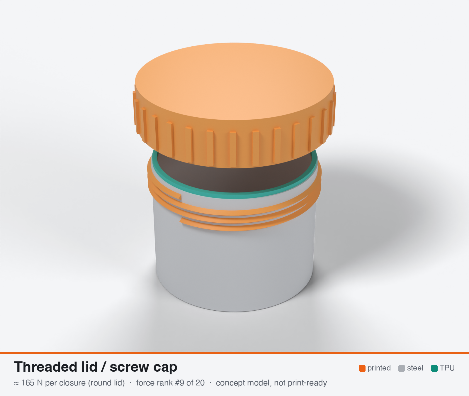
Threaded closure (printed screw cap or threaded ring) with end-face TPU ring
Round lids only. The force below is for one whole closure, not one latch on a rectangular lid.
- Force rank
- 9 of 20
- Build
- Fully printed
- Hand force to close
- ≈ 85 N
- Adjustable preload
- yes
- Positive compression stop
- yes
- Force basis
- calculated
- Review verdict
- corrected
- Confidence
- medium
Verdict: Round caps of 50 mm or less only. Force is torque-limited (about 3 Nm drives about 165 N because TPU face drag dominates). Thread-root bending across layers caps the structure near 400 N, not 1 kN. About 1 N/mm on the 157 mm ring, below the 2-4 N/mm window.
On this page
- Parts
- Print files
- How it works
- Mechanical advantage
- What limits the force
- Analyst's calculation
- Adversarial review
- Calibration adjustments
- Preload retention outdoors
- Materials
- Hardware notes from the research
- Design guidelines
- Failure modes
- Existing designs and commercial references
- Evidence gathered in the sweep
- Sources
Parts
Per closure: 2 parts to print, 2 items to buy and the TPU 85A seal. Parts marked † are not drawn in the 3D model. In the 3D gallery you can click a part to see where it sits. The last column links the print file, or an example of the part in a shop (see the shopping list).
| Part | Qty | Type | What to use | File or shop |
|---|---|---|---|---|
| Jar with thread | 1 | ASA, upright; 3 mm pitch thread, 3 turns; the inner lip on the rim is the hard stop | jar.stl | |
| Screw cap | 1 | ASA, upside down; internal thread, 30 grip ribs | cap.stl | |
| Seal ring | 1 | Seal (TPU 85A) | TPU 85A, 1.4 × 3.2 mm, on the jar rim outside the lip; 0.8 mm squeeze | seal-ring.stl |
| Slip washer (optional) † | 1 | Buy | PTFE or PE, between the seal and the turning cap | S-Polytec |
| Lock (optional) † | 1 | Buy | M4 A4 spring plunger, or a printed pawl | Leschhorn |
Print files
Download all print files for this closure (ZIP, 0.2 MB)
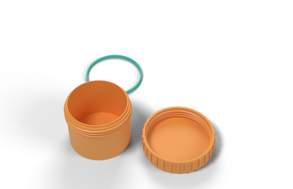
Print in ASA (TPU 85A for the seal), 0.2 mm layers, at least 4 walls; settings and the clearances used are in print/README.md. The parts are already turned the right way up for printing.
| File | Material | Qty | Size (mm) | How to print |
|---|---|---|---|---|
| jar.stl | ASA | 1 | 63 × 63 × 48.4 | Upright, no supports. 3 mm pitch thread; the inner lip on the rim is the hard stop. |
| cap.stl | ASA | 1 | 70 × 69.8 × 17 | Upside down, no supports; use 0.15 mm layers if the thread droops. |
| seal-ring.stl | TPU 85A | 1 | 59.7 × 59.7 × 3.2 | TPU 85A, 100 % infill. Sits on the jar rim outside the lip; the cap squeezes it 0.8 mm. |
All printed parts in their assembled positions, for CAD: threaded-lid-cap.step.
How it works
A coarse 30-degree trapezoidal (or buttress) thread on a round cap converts hand torque into axial force on a TPU 85A ring held on the end face; the thread is self-locking (lead angle about 1.6 deg versus a friction angle of 8-14 deg) so the cap holds without a detent, and it is a single closure (no latch pitch problem, force is spread evenly round the circle). The seal must be on the end face because a thread alone has a helical leak path. Force is set by hand torque, not by the thread strength: friction in the thread and, above all, the TPU ring scrubbing on its mating face eat most of the torque.
Mechanical advantage
Ideal (frictionless) T/F = lead/2pi = 0.64 mm for a 4 mm lead, i.e. an ideal ratio of about 63:1 at a 40 mm wing lever. With thread friction mu 0.25 the real T/F is 6.6 mm (ratio about 6:1; efficiency about 10 percent); mu 0.15 gives 4.2 mm. Adding TPU end-face drag (mu_c 0.5 at r_c 23 mm = 11.5 mm) gives T/F about 18 mm, a ratio of about 2:1. (all own calc, formula from https://en.wikipedia.org/wiki/Leadscrew)
What limits the force
In practice the achievable closing force is limited by hand torque (2-4 Nm) divided by thread plus TPU-face friction (T/F 6.5-26 mm), not by the printed thread, which can sustain more than 1 kN for a 50 mm cap with 3 engaged turns. The 1.8 kN peak is a structural estimate (thread/skirt delamination across layers); the force a hand can actually put on it is only about 600-700 N at best.
Analyst's calculation
Analyst's sustained estimate: 100–450 N, typical 180 N; peak 1800 N.
ASSUMED PART (own): 50 mm major diameter, 30 deg trapezoidal thread, depth 2.0 mm, mean diameter d_m 46 mm, lead = pitch 4 mm (single start), 3 engaged turns (12 mm), skirt wall 4 mm, ASA, 5 perimeters, 0.2 mm layers, axis vertical (worst layer orientation). Lead angle = atan(4/(pi*46)) = 1.59 deg; flank half-angle 15 deg.
- Torque to axial force (formula from https://en.wikipedia.org/wiki/Leadscrew, own arithmetic): T = F (d_m/2) (mu sec(a) + tan(l)) / (1 - mu sec(a) tan(l)). Friction values plastic/plastic 0.25, plastic/steel 0.15 (https://elesa.com/en/elesab2bstoreca/Clamping-handles--Cam-levers--GN9272-A--d1). T/F = 6.6 mm at mu 0.25 and 4.2 mm at mu 0.15; frictionless T/F is 0.64 mm, so the thread is only about 10 percent efficient. Self-locking margin is large (mu sec(a) = 0.26 versus tan(l) = 0.028).
- TPU end-face drag (own; mu_c is NOT sourced, assumed 0.3-0.8 for TPU 85A on ASA, 0.1 with a PE/PTFE slip washer): the cap rotates on the TPU ring at r_c about 23 mm, adding 7-18 mm to T/F (2.3 mm with a slip washer). This term is missing from the simple thread-only torque numbers and it dominates.
- Hand torque 2-4 Nm (two-wing cap, about 40 mm lever x 50-100 N). Axial force at 3 Nm: best case (thread mu 0.15 + slip washer) 460 N; thread only (no scrub) 452 N; typical (mu_t 0.25, mu_c 0.5) 165 N; worst (0.30 / 0.8) 114 N. At 2 Nm and 4 Nm scale by 0.67 and 1.33. Delivered force therefore spans about 75-610 N, typically 110-220 N.
- Structural check (own plus measured anchor): flank projected bearing area = pi462.0*3 = 867 mm2; across-layer sustained allowable about 2 MPa (project brief) gives about 1.7 kN. Skirt tension area about 680 mm2 gives about 1.4 kN. Measured anchor: PETG 1/2-20 threads printed vertically failed at about 80 lbf (about 356 N) per engaged turn, by a roughly 20 deg cone through the outer wall (https://3dprintingspace.com/t/thread-strength-testing/7351), i.e. about 8.9 N per mm of circumference per turn; scaled to 3 turns x pi x 46 mm = about 3.9 kN in PETG; x 0.68 for ASA versus PETG in standing-hook tests (17 vs 25 kg, https://cnckitchen.com/blog/comparing-pla-petg-amp-asa-feat-prusament) = about 2.6 kN; I take 1.8 kN as peak after a roughly 30 percent haircut for untested scale-up and stair-stepped flanks. So the thread is not the limit below about 0.5 kN.
- Result: sustained low/typical/high = 100 / 180 / 450 N (2 Nm with heavy TPU drag / 3.3 Nm typical / best-friction case); peak 1800 N structural. On the 157 mm end-face ring that is 0.6 / 1.1 / 2.9 N/mm against the 2-4 N/mm design window, so only the best-friction case reaches it. Line load per unit torque scales roughly as 1/d^2: a 40 mm cap does about 1.6x better, a 70 mm cap about 2x worse at the same hand torque. Evidence caveat: further web searches were blocked (search budget exhausted); the above rests on direct page fetches only, and no test of a printed ASA cap with a TPU ring was found.
Adversarial review
I recomputed everything from the formulas. Lead-screw T/F with the sec(alpha) term, taken from the Wikipedia Leadscrew page, gives 6.64 / 4.23 mm at mu 0.25 / 0.15. Adding TPU drag mu_c x r_c (0.5 x 23 = 11.5 mm), 3 Nm gives 165 N, which matches the analyst's typical of 180 within 10 percent. Sensitivity: mu_c 0.3 gives 222 N, 0.8 gives 120 N, and best case (grease plus slip washer, 3 Nm) gives 460 N (2.9 N/mm on the 157 mm ring). I checked the thread tooth as a cantilever in bending across layers (1.0 MPa at 450 N, before Kt). I also checked skirt tension (680 mm2 x 2 MPa = 1.36 kN, correct). The analyst's tooth and skirt checks use the wrong failure mode for the thread, and that is what I corrected. Verdict is corrected because the structural claim of more than 1 kN is wrong, even though the typical force lands within about 10 percent. Source checks: 3dprintingspace.com thread test is live and consistent (PETG 80 lbf per thread, 3 threads 240 lbf, about 20 deg cone, PLA about 150 lbf per thread). It is a 1/2-20 fine thread with a 14 mm ID recess, so scaling to 50 mm coarse ASA is an extrapolation. CNC Kitchen hook test confirmed (ASA 57 lying / 17 standing kg, PETG 55/25). Ultrafuse TDS extracted locally: compression set 26 percent at 23 C/72 h and 52 percent at 70 C/24 h (ISO 815), tear 80/18/30 kN/m, break stress 34 vs 10 MPa. All match. Elesa friction values (0.25 plastic/plastic, 0.15 plastic/steel) confirmed. MM Science abstract confirmed (45 deg highest strength, formed threads unsatisfactory, M10 nut above 14.7 MPa). The Polymaker ASA TDS was read locally: XY 43.8, Z 32 MPa, Z elongation 1.65 percent, HDT 100.2 C, Tg 97.8 C. Its specimens were printed with a 70 C chamber and 100 percent infill and the sheet says not to use them for design, so the 73 percent Z/XY ratio overstates real parts. I did not find any source for printed-thread torque-to-clamp performance; no test of an ASA cap with a TPU ring exists in what was available.
Issues raised:
- Torque-to-force arithmetic is right (recomputed T/F: 6.64 mm at mu 0.25, 4.23 mm at 0.15; frictionless 0.64 mm). With TPU end-face drag at mu_c 0.5 and r_c 23 mm, 3 Nm gives 165 N (analyst: 165-180). Using d_m 48 mm, which is what a 50 mm major diameter with 2 mm depth gives, changes this by only about 2 percent.
- The dominant term, TPU 85A on ASA friction mu_c, is unsourced. My search budget was exhausted, so I could not source it. Dry 85A TPU on smooth plastic is plausibly 0.6-1.0, not 0.5. At mu_c 0.8 the force is 120 N, and at mu_t 0.35 (layer-lined FDM thread rather than injection-moulded plastic) it is about 145 N. So typical is trimmed from 180 to 165 N and low from 100 to 90 N. The sustained figure is torque-limited, not strength-limited.
- The claim that the printed thread can sustain more than 1 kN is refuted. It rested on flank bearing area (867 mm2 x 2 MPa), which is not the failure mode. Tooth-root bending across layers is. For a 4 mm pitch tooth (root about 2.4-2.5 mm, depth 2 mm, load at mid-depth) the nominal root stress is about 1.0 MPa at 450 N over 3 uniformly loaded turns. With Kt 2-2.5 that is 2.1-2.6 MPa, already at or above the 2 MPa across-layer sustained allowable. The real structural sustained ceiling is about 380-480 N, and less with the usual first-turn load concentration. So the 450 N high case is capped at 400 N. It also needs grease plus a slip washer plus about 3 Nm, which is 37 N per finger on 40 mm wings.
- The 1.8 kN peak extrapolates a 1/2-20 PETG fine-thread forum test (80 lbf per turn, about 20 deg cone, confirmed on the page) to a 50 mm coarse ASA thread. My own check is 12.7 MPa (29 percent of Polymaker's 43.8 MPa XY) divided by Kt 2-2.5 and spread over 3 turns. That gives 2.2-2.8 kN with perfectly uniform load, but only about 1.8-2.3 kN if the first turn carries about 40 percent. With the room-temperature data flattered (see the Polymaker note below), I take 1.4 kN. Peak is not deliverable by hand: 1.4 kN at T/F 18 mm is about 25 Nm.
- The hand-torque input is borderline. 2-4 Nm needs a two-wing couple of 25-50 N per finger on 40 mm arms, which is the top of the 20-50 N comfortable range. A single-point 50-100 N, as the lever arithmetic is written, is unrealistic. The 80 mm wing span and 50 mm diameter also exceed the 70 x 35 x 30 mm reference envelope, and it only suits round openings of about 50 mm or less.
- Scale limit: line load times circumference needs force that grows with diameter, and torque grows with diameter squared. A 100 mm cap at 2 N/mm needs about 628 N x 31 mm, roughly 19 Nm, which is not by hand. Seal suitability is therefore lowered from 5 to 4. The typical 0.6-1.1 N/mm is below the 2-4 N/mm window.
- Cold: at -20 C the 85A modulus is about 2x, so at a hard stop the closing torque rises 1.5-2x. Fixed-stop closure may be hand-limited short of the stop in winter. This is not addressed.
- The flank is 15 deg off horizontal, which is a roughly 75 deg overhang from vertical for the downward-facing flank. Printability stays at 6 but needs a note: use a buttress thread with a 45 deg trailing flank, or accept stair-stepped flanks.
- Usability is lowered from 7 to 6. Closing needs 3+ full turns, about 43 N per finger, scrubs a TPU ring, and has the cold-stiffening penalty above.
Calibration adjustments
- comparability basis: per latch → per closure (single round cap, 50 mm or less). One cap carries the whole 157 mm ring, and torque scales as diameter squared, so the figure does not extend to larger lids. Value unchanged (165 N); ranked on the number but not offered as a rectangular-lid latch.
Preload retention outdoors
Fair to poor. On a hard shoulder the cap is a rigid fixed-travel closure and loses roughly 30-58 percent of force when 85A TPU sets in hot sun (Ultrafuse 85A set 52 percent at 70 C, https://www.dream3d.co.uk/wp-content/uploads/2022/12/Ultrafuse_TPU_85A_TDS_EN_v2.5.pdf). Without a shoulder the cap can simply be re-tightened, which recovers the loss. ASA thread flanks also relax under sustained hot load, and vibration or thermal cycling can back the cap off despite the static self-lock. A series spring (wave washer or steel spring ring under the TPU) would cut the loss to about 10 percent (own calc, method from the project brief).
Materials
ASA (default; UV stable, HDT about 100 C). UV-stabilised PC could raise structural margins about 1.3-1.5x (own judgement, unmeasured) but does not raise the hand-torque-limited force. Avoid PETG and PETG-CF (HDT 68 C is at the sun-heated surface temperature), avoid PA6-CF (3.3 percent water uptake). PAHT-CF acceptable but creeps.
Hardware notes from the research
None required (fully printed). Optional but recommended: PE or PTFE slip washer (or grease) between the TPU ring and the rotating face to cut end-face drag; A2/A4 stainless spring plunger or printed pawl as a lock; a wave washer as a series spring. A rubber O-ring in a radial gland is a better seal than a printed TPU ring, because the thread then carries no sealing load.
Design guidelines
- Thread: 30 deg trapezoidal or buttress, pitch 4-5 mm, depth 1.6-2.0 mm, 0.3-0.4 mm flank clearance for FDM, at least 3 (preferably 4) engaged turns, plus a 3-5 mm cylindrical pilot spigot so the cap cannot cock and squeeze the gasket unevenly.
- Skirt wall at least 4 mm outside the thread root, 5+ perimeters, 0.16-0.2 mm layers; thread axis vertical keeps the sealing faces flat, but if the part allows, a horizontal or 45 deg axis is stronger (45 deg was strongest for ASA nuts, https://www.mmscience.eu/journal/issues/june-2025/articles/analysis-of-3d-printed-metric-nuts-manufactured-by-the-mex-method-from-asa-material).
- Seal on the end face with a narrow rib (1.2-1.6 mm wide, at least 2 mm tall) rather than a wide bead, and keep the TPU ring on the non-rotating part; place a PE/PTFE slip washer or a polished, ironed land on the rotating face.
- Add a hard shoulder so the cap bottoms at about 0.75-0.8 x free rib height of squeeze; accept that a shoulder removes re-tightening, or leave 0.5 mm of adjustable gap and use a lock.
- Give the cap wings or a lever of at least 35-40 mm radius; do not rely on a 25 mm knurled rim (it needs about 130 N tangential force for the typical load).
- Add a lock against unscrewing: a flex-tooth ratchet or an A4 spring plunger in a 2-3 mm detent.
- Size the cap so the required line load is met: force needed = 2-4 N/mm x circumference, e.g. 314-628 N for a 50 mm cap; above about 50 mm diameter hand torque is not enough.
- Round fillets (R at least 1 mm) at thread runouts and the skirt to cap transition; no sharp internal corners (ASA is only about 3 kJ/m2 notched Charpy at -30 C, per the brief).
Failure modes
- TPU ring scrubbing and twisting during closing: rib rolls, tears (printed TPU 85A edge-on tear only 18-30 kN/m) or wears, and friction eats 60-75 percent of the torque.
- Thread-root or skirt delamination across layers in hot sun when over-tightened (vertical print).
- Cross-threading or cocking, giving uneven squeeze and a leak path on one side.
- Loss of preload from TPU compression set and thread-flank creep (52 percent set at 70 C).
- Cap backing off with vibration or thermal cycling; or seizing from dirt, ice or sun-softened threads.
- Brittle cracking of the skirt in cold if there are sharp corners.
- Helical leak path if the seal is placed on the thread instead of the end face.
Existing designs and commercial references
- Container: sealable, screwable, scaleable, strong (Printables) — Screw container with a TPU 95A seal per the lead; returned HTTP 403 to my fetch so not re-verified; no force data
Evidence gathered in the sweep
SUSTAINED (own est., whole cap, low confidence): 100-300 N total axial; PEAK ~450-730 N. AXIAL FROM TORQUE (own calc): 50 mm cap, 4 mm lead, 2 / 3 / 4 Nm gives ~250-370 / 380-550 / 510-730 N for mu 0.3-0.2, which is only ~1.6-4.6 N/mm on a 157 mm circumference. TESTS: PETG 1/2-20 specimens split at the outer wall at ~100-110 lbf (~450-490 N) per thread, anecdotal https://3dprintingspace.com/t/thread-strength-testing/7351 ; PLA+ 1/4-20 pulled at 48 lbf (10 % infill), 68 (25 %), 90 (50 %), >110 lbf (100 %), reader-reported https://hackaday.com/2023/11/10/putting-3d-printed-screw-threads-to-the-test ; printed cap split along layers under bolt force https://hackaday.io/project/12125/log/41900 ; helical gap leaks https://forums.autodesk.com/t5/fusion-design-validate-document/water-tight-threads-not-working-correctly/m-p/11662111 ; ASA nut study (abstract) https://www.mmscience.eu/journal/issues/june-2025/articles/analysis-of-3d-printed-metric-nuts-manufactured-by-the-mex-method-from-asa-material ; sealed screw container with TPU 95A https://printables.com/model/1233019-container-sealable-screwable-scaleable-strong-3-ve ; one study found printed connectors <30 % of expected clamping force (exact page not pinned down) https://www.ncbi.nlm.nih.gov/pmc/articles/PMC9781732/ . CONFIDENCE: low.
Sources
- 3D Printing Space: thread strength testing — Fetched and verified: PETG 1/2-20 vertical threads about 80 lbf per engaged turn, about 20 deg cone failure through the outer wall; PLA about 150 lbf per turn; forum test, not a lab study
- Hackaday: putting 3D printed screw threads to the test — Fetched: article is qualitative (bottom layers peel); the 48 / 68 / 90 / over 110 lbf by infill figures for 1/4-20 PLA+ are from a reader comment, not the article
- MM Science: 3D printed metric nuts in ASA (abstract) — Fetched abstract: 45 deg build orientation gave highest tensile strength; formed threads unsatisfactory; best nut over 14.7 MPa; no newton values
- Hackaday.io: printed cap splits along layers under bolt force — Fetched: PLA part split along layers under bolt and washer force; no numbers
- Wikipedia: Leadscrew — Fetched: torque and efficiency formulas for Acme-type threads and self-locking condition
- Elesa GN 927.2 page (friction coefficients) — Fetched: plastic/plastic 0.25, plastic/steel 0.15
- PMC9781732: compression of FDM PLA threaded rods — Fetched: this paper is about PLA rods in compression; its under-30-percent clamping-force remark is a cited M12 SLA-resin bolt result, NOT FDM evidence, so it should not be used for printed-thread claims
- CNC Kitchen: comparing PLA, PETG and ASA (Prusament) — Standing-vs-lying hook figures taken from the project brief, not re-fetched
- Ultrafuse TPU 85A datasheet — Compression set 26 percent at 23 C and 52 percent at 70 C, tear anisotropy; figures from the project brief, not re-checked
Sources the reviewer flagged (dead, blocked or misdescribed):
- https://printables.com/model/1233019-container-sealable-screwable-scaleable-strong-3-ve - HTTP 403 for me too; the TPU 95A seal claim is unverified and there is no force data.
- https://3dprintingspace.com/t/thread-strength-testing/7351 - live and accurate, but a fine-pitch PETG test (80 lbf per turn) extrapolated to a coarse 50 mm ASA thread; the PLA 2-thread figure on the page is internally inconsistent (300 vs 204 lbf).
- https://hackaday.com/2023/11/10/putting-3d-printed-screw-threads-to-the-test - the lbf figures are one reader comment (1/4-20, PLA+ per the article), not the article. The analyst already flagged this.
- https://pmc.ncbi.nlm.nih.gov/articles/PMC9781732/ - PLA M42-M64 rods in compression; the under-30-percent clamping remark is a cited study by Wi et al. I could not confirm the analyst's 'M12 SLA resin' detail. Not usable for FDM thread claims, as the analyst said.
- https://cdn.shopify.com/s/files/1/0603/6609/files/PolyLite_ASA_TDS_V5.1.pdf - figures confirmed, but the specimens were printed in a 70 C chamber at 100 percent infill and the sheet says not to design from them.